Chapter 2 Setting Up the Switch
Set Up the Switch (Existing Network)
2-4
User Guide for the Catalyst Express 520 Switches
OL-12761-02
Step 3
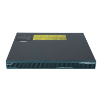
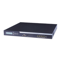
Use the supplied Category 5 Ethernet cable to connect an upstream DHCP server (such as the
Cisco Unified Communications 500 Series) to the switch dual-purpose port.
Before proceeding to the next step, wait until the port LEDs on the switch and the other device
blink green. The solid green port LEDs means a successful connection between the two
devices.
The ADMIN LED should still be blinking green.
Troubleshooting:
If the port LEDs do not blink green or if either LED turns amber, make sure that you are using
the Category 5 Ethernet cable that shipped with the switch. If not, make sure that the cable
that you are using is an undamaged Category 5 Ethernet cable.
S
Y
S
T
A
L
RT
P
o
E
A
D
M
I
N
C
a
t
a
l
y
s
t
E
x
p
r
e
s
s
5
2
0
S
e
r
i
e
s
POW
E
R
OV
E
R
E
T
H
E
R
N
E
T
1
2
3
4
5
6
7
8
1
S
E
E
M
A
N
U
A
L
B
E
F
O
R
E
I
N
S
T
A
L
L
A
T
I
O
N
C
is
c
o
U
n
if
ie
d
5
0
0
S
e
r
ie
s
W
L
A
N
V
M
P
O
E
201615
 Loading...