3-4
Cisco PIX Firewall Hardware Installation Guide
78-15170-01
Chapter 3 PIX 506/506E
Installing the PIX 506/506E
Table 3-2 lists the state of the PIX 506/506E rear panel LEDs.
The USB port at the left of the Console port is not used.
Installing the PIX 506/506E
Place the PIX 506/506E on a flat, stable surface. The PIX 506/506E is not rack mountable.
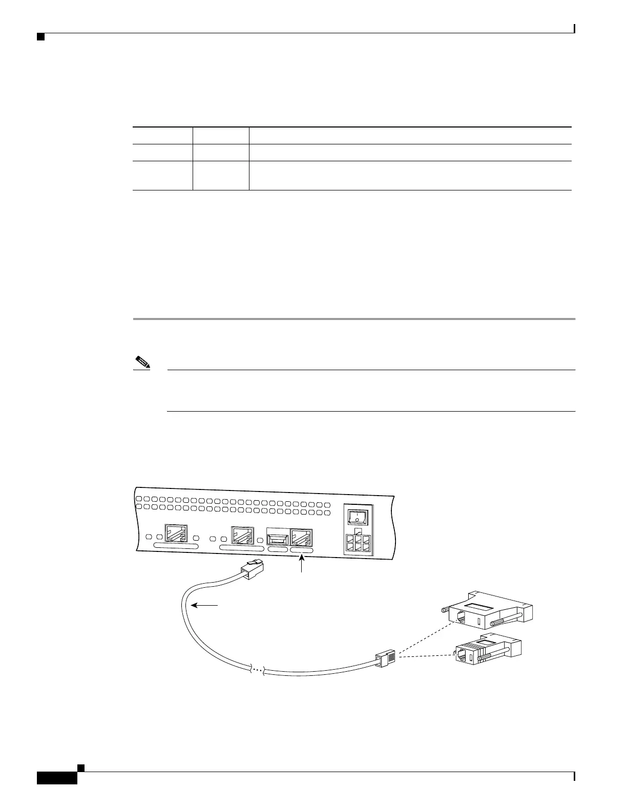
Complete these steps to install the PIX 506/506E :
Step 1 Connect the cable so that you have either a DB-9 or DB-25 connector on one end as required by the serial
port for your computer, and the other end is the RJ-45 connector.
Note Use the RJ-45 Console port to connect a computer to enter configuration commands. Locate the
serial cable from the accessory kit. The serial cable assembly consists of a null modem cable
with RJ-45 connectors, and one DB-9 connector and one DB-25 connector.
Step 2 Connect the RJ-45 connector to the PIX 506/506E and connect the other end to the serial port connector
on your computer.
Figure 3-7 PIX 506 Serial Console Cable
Table 3-2 PIX 506/506E Rear Panel LEDs
LED State Description
ACT On Shows network activity.
LINK On Shows that data is passing on the network to which the connector is
attached.
C
O
N
S
O
L
E
E
T
H
E
R
N
E
T
0
ACT
LINK
LINK
DC
POWER
INPUT
ACT
U
S
B
E
T
H
E
R
N
E
T
1
38853
Console
port (RJ-45)
RJ-45 to
DB-9 or DB-25
serial cable
(null-modem)
Computer serial port
DB-9 or DB-25

 Loading...


