4-10
Cisco PIX Firewall Hardware Installation Guide
78-15170-01
Chapter 4 PIX 515/515E
Installing Failover
Step 6 If you are using Stateful Failover, use one of the following types of connections, that is appropriate for
your system, between the dedicated interfaces on the PIX Firewall units:
• Cat 5 crossover cable directly connecting the primary unit to the secondary unit.
• 100BaseTX half-duplex hub using straight Cat 5 cables.
• 100BaseTX full duplex on a dedicated switch or dedicated VLAN of a switch.
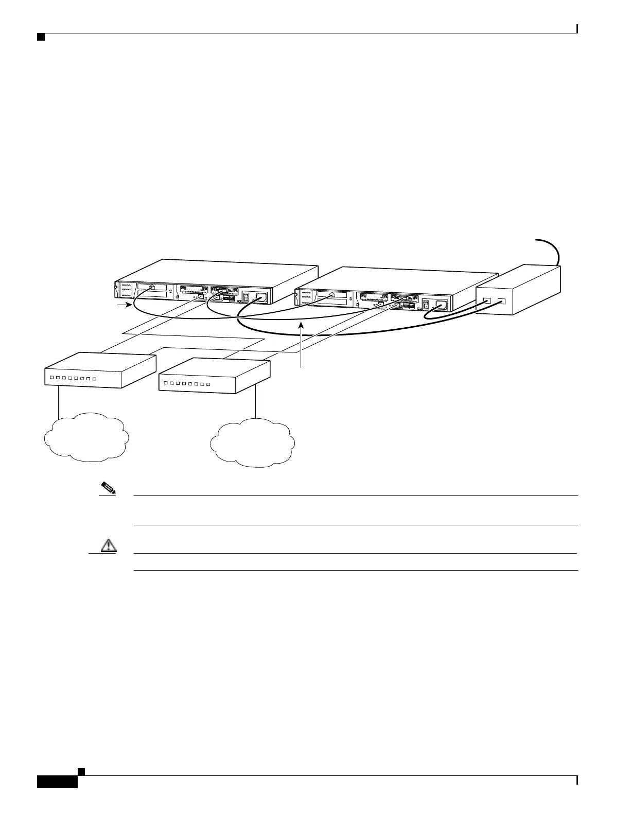
Figure 4-11 shows an example of a minimally configured PIX 515/515E with only the two interfaces on
the motherboard used for network traffic.
Figure 4-11 Failover Connections
Note All enabled interfaces must be connected between the active and standby units. Only configure the active
unit. On the PIX 515/515E, the active unit is indicated by the ACT LED on the front of the unit.
Caution Do not turn the power on until the units are connected and the primary unit is configured completely.
Step 7 Use the power switch at the back of the units to power on the primary unit and then power on the standby
unit.
Within a few seconds, the active unit automatically downloads its configuration to the standby unit.
If the primary unit fails, the secondary unit automatically becomes active.
Inside
network
Internet
D
O
N
O
T
I
N
S
T
A
L
L
I
N
T
E
R
F
A
C
E
C
A
R
D
S
W
I
T
H
P
O
W
E
R
A
P
P
L
I
E
D
C
O
N
S
O
L
E
1
0
/
1
0
0
E
T
H
E
R
N
E
T
0
L
i
n
k
F
D
X
F
D
X
1
0
0
M
b
p
s
L
in
k
1
0
0
M
b
p
s
F
A
I
L
O
V
E
R
1
0
/
1
0
0
E
T
H
E
R
N
E
T
1
PIX-515
D
O
N
O
T
I
N
S
T
A
L
L
I
N
T
E
R
F
A
C
E
C
A
R
D
S
W
I
T
H
P
O
W
E
R
A
P
P
L
I
E
D
C
O
N
S
O
L
E
1
0
/
1
0
0
E
T
H
E
R
N
E
T
0
L
in
k
F
D
X
F
D
X
1
0
0
M
b
p
s
L
in
k
1
0
0
M
b
p
s
F
A
I
L
O
V
E
R
1
0
/
1
0
0
E
T
H
E
R
N
E
T
1
PIX-515
27883
PIX 515
Primary unit
Stateful Failover
dedicated interface
cable
Failover
serial cable
PIX 515
Standby unit
UPS
(not supplied)
Power
Inside switch
Outside switch

 Loading...


