4-19
Cisco PIX Firewall Hardware Installation Guide
78-15170-01
Chapter 4 PIX 515/515E
Installing a Circuit Board in the PIX 515/515E
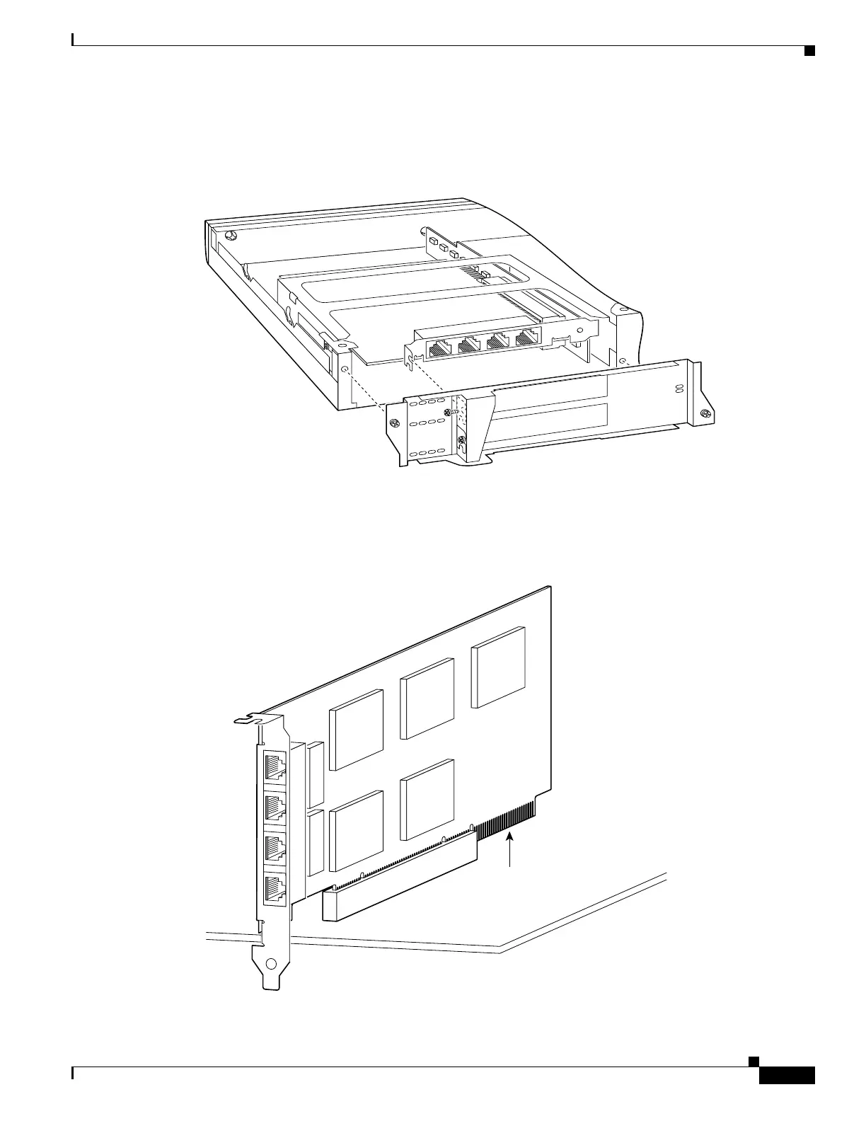
Step 4 Attach the back cover plate making sure that the connecting flange on the circuit board goes through the
slot on the back cover plate as shown in Figure 4-22.
Figure 4-22 Attaching PIX 515/515E Back Cover Plate
Step 5 Attach the screw to hold the circuit board’s connecting flange to the cover plate, and install the screws
to attach the cover plate to the PIX 515/515E unit.
Step 6 Reattach the top panel.
Figure 4-23 4-Port Circuit Board Overlap
61905
27884
Overlap

 Loading...


