4-21
Cisco PIX Firewall Hardware Installation Guide
78-15170-01
Chapter 4 PIX 515/515E
Installing the PIX 515/515E DC Model
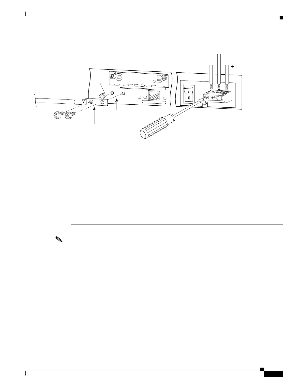
Figure 4-24 Attaching a Grounding Lug to the PIX Firewall
Step 5 Power off the unit. Ensure that power is removed from the DC circuit. To ensure that all power is OFF,
locate the circuit breaker on the panel board that services the DC circuit, switch the circuit breaker to
the OFF position, and tape the switch handle of the circuit breaker in the OFF position.
Step 6 Strip the ends of the wires for insertion into the power connect lugs on the PIX 515/515E.
Step 7 Insert the ground wire into the connector for the earth ground and tighten the screw on the connector.
Refer to Figure 4-24 and using the same method as for the ground wire, connect the negative wire and
then the positive wire.
Step 8 After wiring the DC power supply, remove the tape from the circuit breaker switch handle and reinstate
power by moving the handle of the circuit breaker to the ON position.
Step 9 Install any remaining interface boards as described in “Installing a Circuit Board in the PIX 515/515E”.
Step 10 Power on the unit from the switch at the rear of the unit.
Note If you need to power cycle the DC PIX 515/515E, wait at least 5 seconds between powering off the unit
and powering it back on.
Link
FDX
100 Mbps
10/100 ETHERNET 1
27885
Grounding holes on
PIX Firewall DC model
Ground wire wire
2-hole copper
standard barrel
grounding lug
8-32 screws
To rack
ground
wire

 Loading...


