Fan status LED7Drive bays 1 – 10 support Serial Attached SCSI
(SAS) and Serial Advanced Technology
Attachment (SATA) hard disk drives (HDDs) and
solid state drives (SSDs)
1
Network link activity LED8Drive bays 1 – 10 support Non-Volatile Memory
express (NVMe) based Peripheral Component
Interconnect Express (PCIe) SSDs
2
Temperature status LED9Power button or power status LED3
Pull-out asset tag10Unit identification button or LED4
KVM connector
(used with KVM cable that provides one DB-15
VGA, one DB-9 serial, and two USB connectors)
11System status LED5
-Power supply status LED6
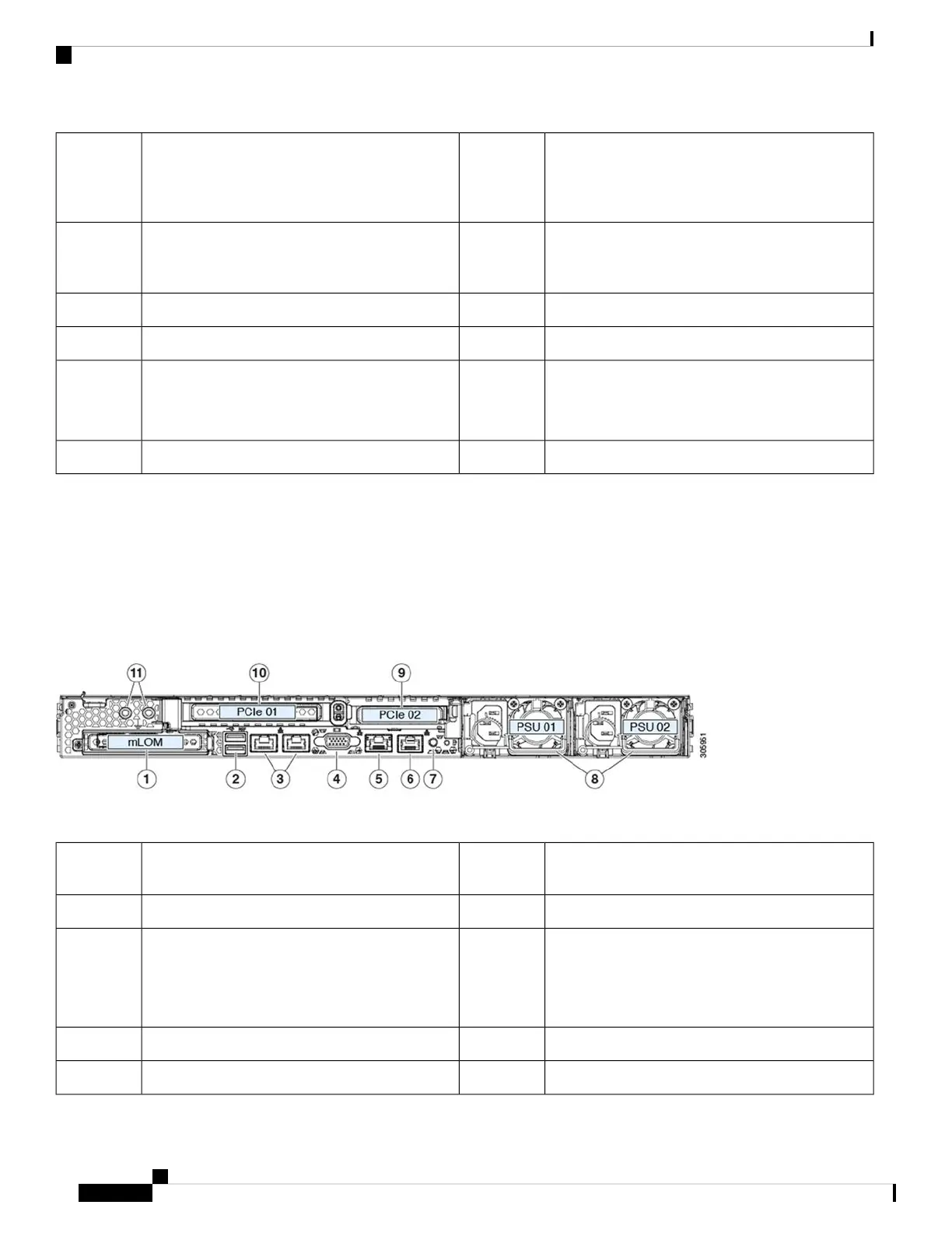
Cisco SNS 3600 Series Appliance Rear Panel Features
The following figure shows the rear panel features of Cisco SNS 3600 series appliance.
For definitions of LED states, see Rear Panel LEDs, on page 8.
Figure 2: Cisco SNS 3600 Series Appliance Rear Panel
Rear unit identification button or LED7Modular LAN-on-motherboard (mLOM) card bay
(x16 PCIe lane)
1
Power supplies (two, redundant as 1+1)8Two USB 3.0 ports2
PCIe riser 2 or slot 2 (x16 lane)
Includes PCIe cable connectors for front-loading
NVMe SSDs (x8 lane)
9Dual 1-Gb or 10-Gb Ethernet ports (LAN1 and
LAN2)
The dual LAN ports can support 1 Gbps or 10 Gbps
depending on the link partner capability.
3
PCIe riser 1 or slot 1 (x16 lane)10VGA video port (DB-15 connector)4
Threaded holes for dual-hole grounding lug111-Gb Ethernet dedicated management port5
Cisco Secure Network Server 3600 Series Appliance Hardware Installation Guide
4
Cisco Secure Network Server 3600 Series Appliance Overview
External Features