2-7
Cisco UCS C220 Server Installation and Service Guide
OL-25760-01
Chapter 2 Installing the Server
Installing the Server In a Rack
b. Push the server into the slide rails until it stops at the internal stops.
c. Push in the plastic release clip on each inner rail (labelled PUSH), and then continue pushing the
server into the rack until its front latches engage the rack posts.
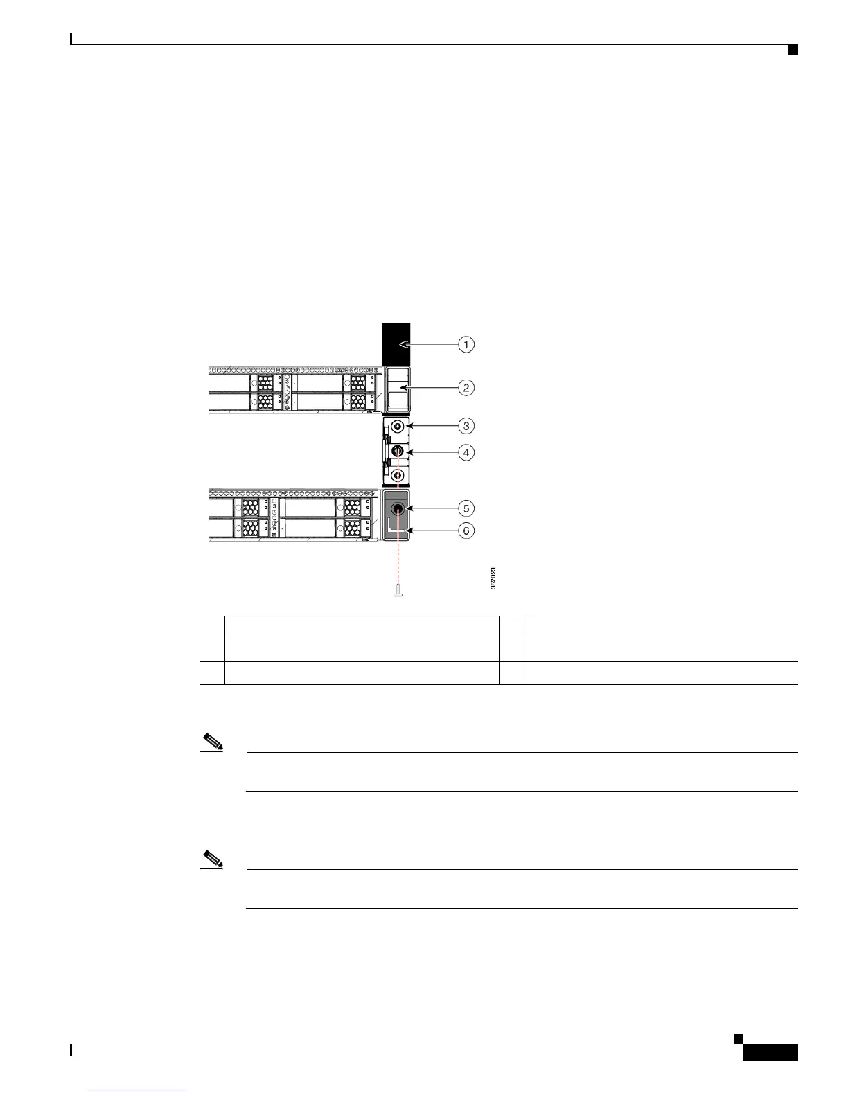
Step 4 Optional: Secure the server in the rack more permanently by using the two screws provided. This might
be desirable if you plan to move the rack with servers installed.
With the server fully pushed into the slide rails, open a
hinged slam-latch lever on the front of the server
and insert the screw through the hole that is under the lever. The screw threads into the static part of the
rail on the rack post and prevents the server from being pulled out. Repeat for the opposite slam latch.
Figure 2-4 Optional Securing Screws
Step 5
Optional: Attach the cable management arm (CMA) to the rear of the slide rails:
Note The CMA is designed for mounting on either the right or left slide rails. These instructions
describe an installation to the rear of the right slide rails, as viewed from the rear of server.
a. Slide the plastic clip on the inner CMA arm over the flange on the mounting bracket that attached
to the side of the server. See Figure 2-5.
Note Whether you are mounting the CMA to the left or right slide rails, be sure to orient the engraved
marking, “UP” so that it is always on the upper side of the CMA. See Figure 2-5.
b. Slide the plastic clip on the outer CMA arm over the flange on the slide rail. See Figure 2-5.
c. Attach the CMA retaining bracket to the left slide rail. Slide the plastic clip on the bracket over the
flange on the end of the left slide rail. See Figure 2-5.
1 Rack post 4 Screw-hole on front end of slide rail
2 Slam-latch on server (closed) 5 Screw-hole on slam-latch when open
3 Front end of slide rail on rack-post 6 Slam-latch on server (open)

 Loading...


