Figure 4: Location of Sensor Connector, Fan Cage, and Midplane Assembly (Top Down View)
Step 5 Disassemble the Midplane PCBA.
a) Using a standard screwdriver, gently pry up the Bus Bar modules at each connector until you can remove them by
hand.
b) Using a screwdriver, rotate each of the screws counter-clockwise until it disengages.
c) Grasp the midplane bracket and remove it by hand.
d) Separate the Midplane PCBA from the midplane bracket by hand.
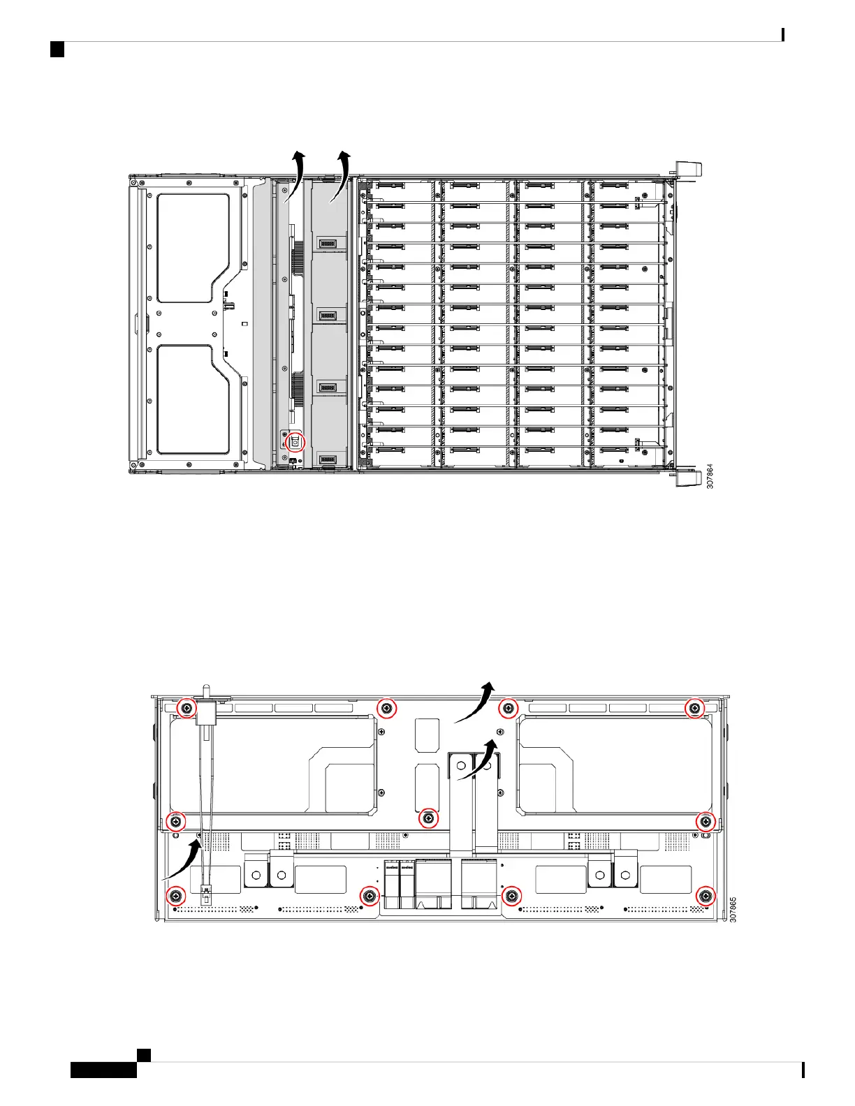
The following image shows the screws and components.
Figure 5: Location of Mounting Screws, Bus Bar Modules, Midplane Bracket, and Midplane PCBA (Top Down View)
Step 6 Remove the drive cage mounting screws from the front of the chassis.
The following illustration shows these screws.
Cisco UCS S3260 Storage Server PCBA Disassembly For Commission Regulation (EU) 2019/424 Service Note
8
Recycling the PCB Assembly (PCBA)
Recycling the PCB Assembly (PCBA)

 Loading...


