3
Chapter 1: Valet
/
Horizontal Placement
The Valet has four rubber feet on its bottom panel. Place
the Valet on a level surface near an electrical outlet.
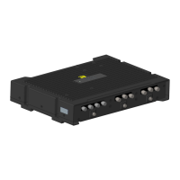
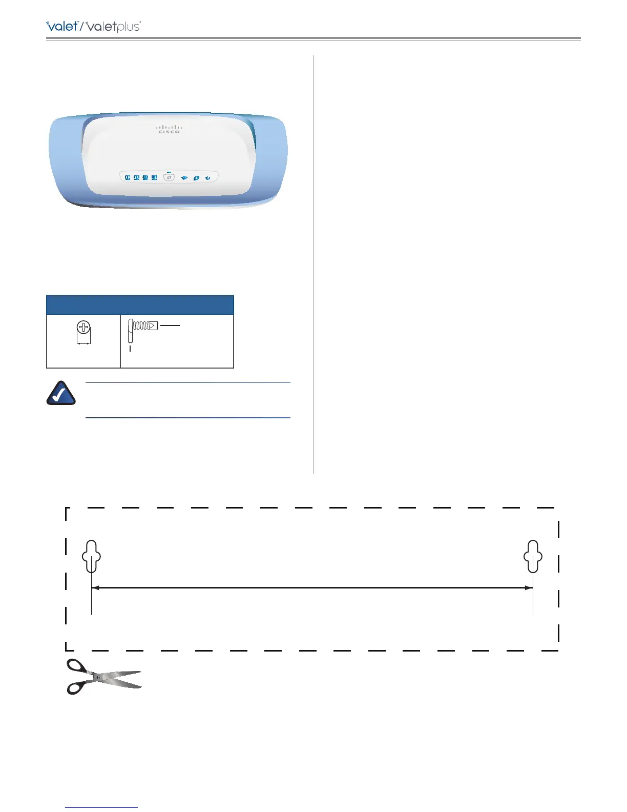
Wall-Mounting Placement
The Valet has two wall-mount slots on its bottom panel.
The distance between the slots is 152 mm.
Two screws are needed to mount the Valet.
Suggested Mounting Hardware
2.5-3.0 mm
4-5 mm 1-1.5 mm
NOTE: Cisco is not responsible for damages
incurred by unsecured wall-mounting hardware.
Wall-Mounting Template
Print this page at 100% size.
Cut along the dotted line, and place on the wall to drill precise spacing.
152 mm
Follow these instructions:
1. Determine where you want to mount the Valet. Make
sure that the wall you use is smooth, flat, dry, and
sturdy. Also make sure the location is within reach of
an electrical outlet.
2. Drill two holes into the wall. Make sure the holes are
152 mm apart.
3. Insert a screw into each hole and leave 3 mm of its
head exposed.
4. Position the Valet so the wall-mount slots line up with
the two screws.
5. Place the wall-mount slots over the screws and slide
the Valet down until the screws fit snugly into the
wall-mount slots.