EasyManua.ls Logo

Cissell HD125 User Manual

Cissell HD125
73 pages
To Next Page IconTo Next Page
Page #1 background imageLoading...
Page #1 background image
THIS MANUAL MUST BE GIVEN TO THE EQUIPMENT OWNER
MAN HD2125 3/06
Technical specifications
Installation instructions
Operating instructions
Maintenance
OWNER'S MANUAL
125 lb. HD LAUNDRY DRYER
Cissell Manufacturing Co.
831 S. First St. - P.O.Box 32270 - Louisville, Ky. - 40232-2270
Tel: (502) 587-1292 - Fax: (502) 585-2333 -
Sales Fax: (502) 585-3625 - Service/Parts Fax: (502) 681-1275
HD125
Gas: Natural and LP
Steam
Electric

Table of Contents

Question and Answer IconNeed help?

Do you have a question about the Cissell HD125 and is the answer not in the manual?

Cissell HD125 Specifications

General IconGeneral
BrandCissell
ModelHD125
CategoryDryer
LanguageEnglish

Summary

Cissell 125 lb. HD Laundry Dryer Owner's Manual

Important Notes and Warnings

Critical safety information and operational precautions for user guidance.

Dryer Warranty Information

Details of the manufacturer's warranty coverage for parts and labor.

Symbols Used in Manual

Explanation of various symbols indicating hazards or functions within the manual.

Dryer Installation and Setup

Unpacking and General Installation

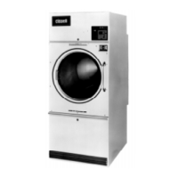
Procedures for unpacking, placement, and initial setup of the dryer.

Dryer Dimensions

Gas Dryer Dimensions

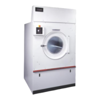
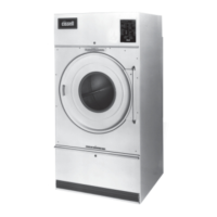
Visual representation of gas dryer dimensions and connection points.

Steam Dryer Dimensions

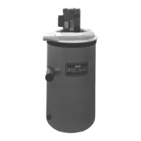
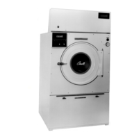
Visual representation of steam dryer dimensions and connection points.

Electric Dryer Dimensions

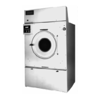
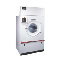
Visual representation of electric dryer dimensions and connection points.

Dryer Specifications

Electrical Connections and Grounding

Gas Piping Installation

Gas Service and Piping Information

Information on gas service, piping, sizing, and installation procedures.

Gas Pipe Size Chart

Table to determine appropriate gas pipe sizes based on demand and length.

Gas Piping Installation Steps

Specific instructions and precautions for installing gas piping.

Steam Piping Installation

Exhaust System Installation

Multiple Exhaust Systems

Guidelines for installing multiple dryers with a shared exhaust system.

Make-Up Air Requirements

Recommended minimum make-up air quantities and duct sizes for various dryer models.

Separate Exhaust Systems

Instructions for installing individual exhaust systems for each dryer.

Safe Operation Practices

Energy Saving Tips

Operating Instructions (Two Timer Models)

Control Panel and Timers

Overview of the dryer's control panel, drying, and cooling timers.

Drying and Cooling Procedures

Step-by-step guide for loading, setting times, and operating the dryer.

Troubleshooting Dryer Issues

Service Saver Tips

Initial checks and common solutions for dryer malfunctions before calling service.

Troubleshooting Charts

Tables listing dryer problems, their causes, and remedies for diagnosis.

Direct-Spark Ignition Operation

Ignition System Explanation

Description of how the direct-spark ignition system functions during operation.

Ignition Operation Flow Chart

Visual representation of the direct-spark ignition sequence and logic.

General Maintenance Schedule

Daily Maintenance Tasks

Daily cleaning and checks for optimal dryer performance.

Periodic Maintenance Checks

Regular inspections and cleaning of components like coils, burners, and motors.

Component Adjustments and Alignment

Burner Air Inlet Adjustment

Procedure for adjusting the burner air inlet for optimal combustion.

Basket Alignment Procedures

Steps to align the dryer basket and spider assembly correctly.

Air Switch Adjustment

Instructions for adjusting the air switch for proper dryer operation.

Advanced Dryer Features and Maintenance

Reversing Control Timer Operation

Instructions for adjusting the reversing timer and motor rotation settings.

Large Gear Reducer Maintenance

Procedures for checking and changing oil in the gear reducer.

Parts Identification - Front View

Parts Identification - Rear View (TM200 Gear Reducer)

TM200 Gear Reducer Parts List

Detailed list of part numbers for the TM200 gear reducer assembly.

Parts Identification - Rear View (Gear Motor)

Gear Motor Parts List

Detailed list of part numbers for the gear motor assembly.

Front Panel Assembly Parts

Thermostat Assembly - 2 Timer Parts

Burner Access Door Parts

Lint Door Assembly Parts

DMP Sensor Assembly Parts

2 Timer Sensor Assembly Parts

Pro Sensor Assembly Parts

ProHC Sensor Assembly Parts

Air Switch Assembly Parts

2 Timer Control Panel Assembly Parts

DMP Control Panel Assembly Parts

Pro Control Panel Assembly Parts

ProHC Control Panel Assembly Parts

Rear Motor Control Assembly Parts

TM200 Gear Reducer Parts

Gas Bonnet Assembly Parts

Steam Bonnet (9-Coil) Parts

Electric Bonnet Parts

Electric Bonnet Components and Specifications

Related product manuals