1) Do not use magnetic brakes to stop or control the rotating output shaft.
2) The driver will be damaged if the driver's BK+ and BK- and magnetic brakes are directly connected.
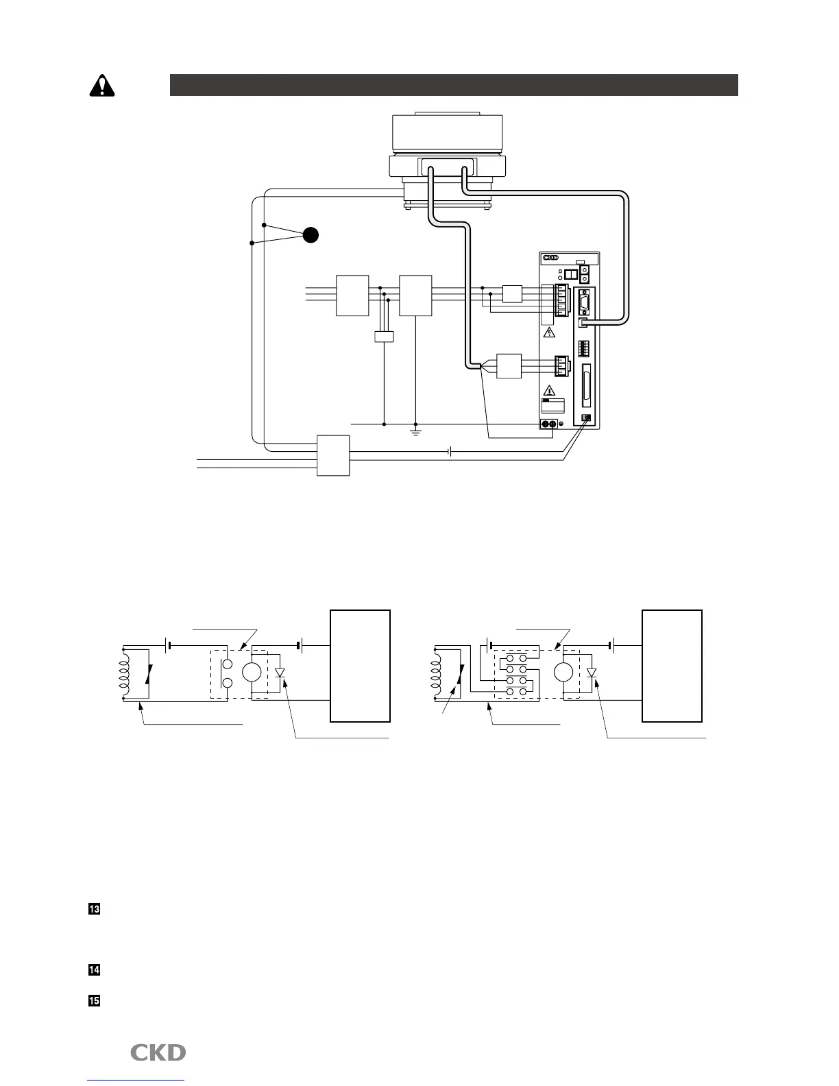
3) When connecting the following inductive load, such as a relay, to the external contact, set the coil's rated voltage to 24
VDC and the rated current to 100 mA or less, and provide measures against surge current.
Recommended circuit for magnetic brakes
• Relay contact serial connection
Operation method
1. Control with NC program (M68, M69)
When the "M68" code is executed, BK+ to BK- will not be
energized (brakes are applied), and when the "M69" code
is
executed, BK+ to BK- will be energized (brakes are
released).
2. Control with brake release input (I/O connector/18 pin)
If brake release is input while the brakes are applied, BK+
to BK- will be energized (brakes are released).
If magnetic brakes are frequently turned on and off, use a
solid-state relay (SSR) for the external contact.
Recommended model G3NA-D210BDC5-24 (OMRON)
Refer to the SSR instruction manual before using.
Check that relay contact capacity is 10 times or more than
the rated current. If less, use a multiple relay and use two
or more relay contacts serially. Reed life can be extended.
When passing a shaft through the hollow hole in the type with magnetic brakes, use a non-magnetic material
(SUS303, etc.).
If magnetic material (S45C, etc.) is used, the shaft will be magnetized. This could cause iron powder to stick on the
device or the peripheral devices to be affected by the magnetic properties.
Note that around the magnetic brakes, iron powder, etc., could be attracted by the magnetic properties, or
measuring instruments, sensors and other devices could be affected.
Refer to the Technical Documents of the Absodex AX Series TS,TH type driver for other precautions.
 Loading...