Description Specifications
Communication
protocol
PROFIBUS DP-V0 compliant
I/O data Input 8 byte/output 8 byte
Communication
speed
12M/6M/3M/1.5M/500k/187.5k/
93.75k/45.45k/19.2k/9.6kbps
(auto baud rate function)
Connection
cable
PROFIBUS cable
(shielded 2 wire twisted pair cable)
Node address 0 to 125 (set with parameter)
Connection
quantity
Without repeater:
Max. 32 stations for each segment
With repeater
Max. total of 126 stations
Monitor function
Current position (degrees,. pulse),
position deviation, program no.,
electric thermal, rotation speed,
alarm
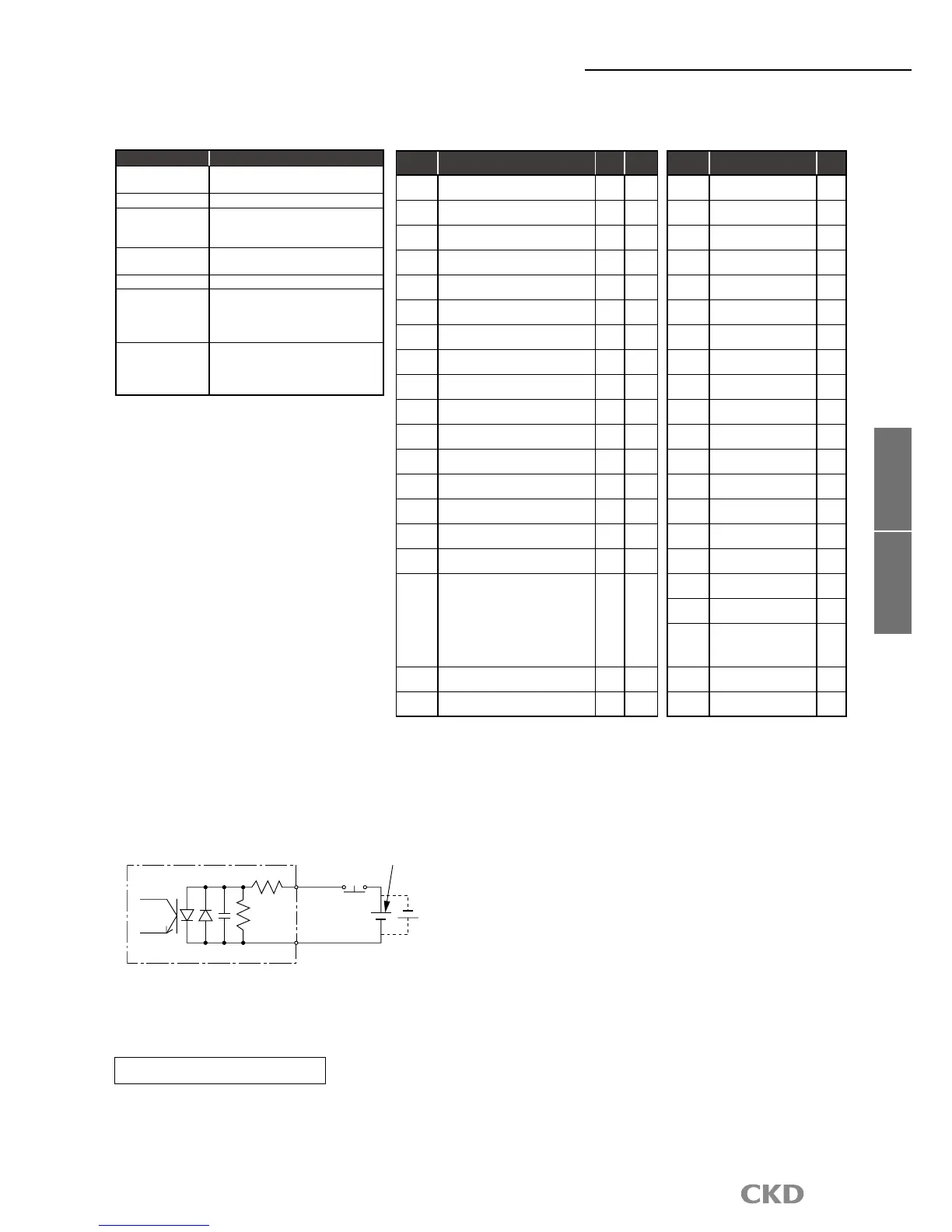
Communication specifications
EMG+
External power DC24
(not included)
Rated voltage 24V±10%, rated current 5mA or less
*
*External power supplycan be
used with the polarity reversed
EMG-
+24V
TB3 input circuit specifications (emergency stop)
Refer to materials such as “Installation Guideline for PROFIBUS DP/FMS” for details on laying the cables.
I/O signal
Byte
No.
Signal name
Logic
Judgment
0.0
Program no. selection input (bit 0)
Positive
Level
0.1
Program no. selection input (bit 1)
Positive
Level
0.2
Program no. selection input (bit 2)
Positive
Level
0.3
Program no. selection input (bit 3)
Positive
Level
0.4
Program no. selection input (bit 4)
/program no. setting input the second digit
Positive
Level
edge
0.5
Program no. setting input the first digit
/program no. selection input (bit 5)
Positive
Level
edge
0.6 Reset input
Positive
Edge
0.7 Return to origin command input
Positive
Edge
1.0 Start input
Positive
Edge
1.1
Servo on input
/program stop input
Positive
Level
edge
1.2
Ready return input
/continuous rotation stop input
Positive
Edge
1.3
Answer input
/position deviation count reset
Positive
Edge
1.4 Emergency stop input
Negative
Level
1.5 Brake release input
Positive
Level
1.6 Not available
1.7 Not available
2.0
to
2.5
Not available
2.6 Monitor output action request
Positive
Level
2.7 Command execution request
Positive
Edge
Byte
No.
Signal name
Logic
0.0 M code output (bit 0)
Positive
0.1 M code output (bit 1)
Positive
0.2 M code output (bit 2)
Positive
0.3 M code output (bit 3)
Positive
0.4 M code output (bit 4)
Positive
0.5 M code output (bit 5)
Positive
0.6 M code output (bit 6)
Positive
0.7 M code output (bit 7)
Positive
1.0 Inposition input
Positive
1.1
Positioning complete
output
Positive
1.2
Start input waiting
output
Positive
1.3 Alarm output 1
Negative
1.4 Alarm output 2
Negative
1.5
Output during indexing 1
/origin position output
Positive
1.6
Output during indexing 2
/servo state output
Positive
1.7 Ready output
Positive
2.0 Output
Positive
2.1 M code strobe output
Positive
2.2
to
2.5
Not available
2.6 Monitor medium
Positive
2.7
Command completion
Positive
Safety precautions
PROFIBUS-DP specification
PLC
→
AX(Input)
AX
→
PLC(Output)
 Loading...