Do you have a question about the CKD EVD Series and is the answer not in the manual?
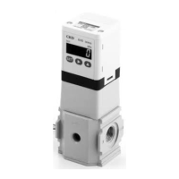
Covers microcomputer-based functions like error display, zero/span, direct memory, and switch output.
Emphasizes proper handling, adherence to specifications, and corporate standards for device safety.
Covers power voltage, wiring integrity, DC supply, stopping machinery, and short-circuit risks.
Covers port sealing, pipe flushing, tape application, torque, and leak detection.
Precautions for air supply type, cleanliness, service shutdown, and immediate response to abnormalities.
Internal circuit and load connection examples for analog input types.
Pinout diagram for analog input connections on the product body.
Internal circuit and load connection examples for parallel input types.
Pinout diagram for parallel input connections on the product body.
Details the display for selecting input signal type and target value.
Shows display for confirming zero/span adjustment validity and settings.
How to enter F1 mode for analog/parallel input and direct memory settings.
Procedure for setting values using the preset memory input mode.
Procedure for setting values using the direct memory input mode.
Setting options for full scale or adjusted zero/span.
Options to disable or enable automatic power off.
Settings for disabling or enabling switch output modes 1 and 2.
Lists common error codes (E001-E005) and their corresponding causes.
Provides specific actions and checks to resolve detected errors.
| Brand | CKD |
|---|---|
| Model | EVD Series |
| Category | Controller |
| Language | English |