Maintain sufficient distance between the communication cable and the power and motor cable.
Do not bundle communication and power cable as it may cause communication errors and failures due to
instability caused by noise.
Refer to materials such as DeviceNet laying manual for details on laying the cables.
Safety precautions
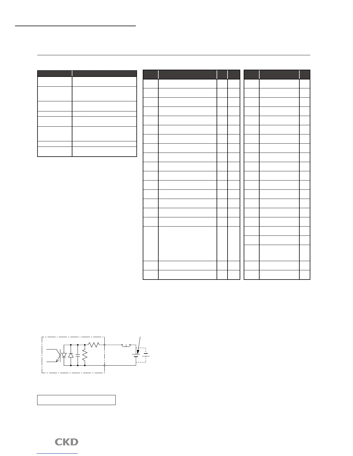
I/O signal
Byte
No.
Signal name
Logic
Judgment
0.0
Program no. selection input (bit 0)
Positive
Level
0.1
Program no. selection input (bit 1)
Positive
Level
0.2
Program no. selection input (bit 2)
Positive
Level
0.3
Program no. selection input (bit 3)
Positive
Level
0.4
Program no. selection input (bit 4)
/program no. setting input the second digit
Positive
Level
edge
0.5
Program no. setting input the first digit
/program no. selection input (bit 5)
Positive
Level
edge
0.6 Reset input
Positive
Edge
0.7 Return to origin command input
Positive
Edge
1.0 Start input
Positive
Edge
1.1
Servo on input
/program stop input
Positive
Level
edge
1.2
Ready return input
/continuous rotation stop input
Positive
Edge
1.3
Answer input
/position deviation count reset
Positive
Edge
1.4 Emergency stop input
Negative
Level
1.5 Brake release input
Positive
Level
1.6 Not available
1.7 Not available
2.0
to
2.5
Not available
2.6 Monitor output action request
Positive
Level
2.7 Command execution request
Positive
Edge
Communication specifications
Descriptions Specifications
Power supply for
communication
11 to 25 VDC
Current consumption
of power supply for
communication
50mA or less
Communication
protocol
DeviceNet compliant: remote I/O
Occupying nodes Input 8 byte/output 8 byte
Communication speed
500k/250k/125kbps
(Select with the parameter setting.)
Connection cable
DeviceNet compatible cable
(Shielded 5 wire cable,
2 signal lines, 2 power lines, 1 shield)
Node address 0 to 63 (set with parameter)
Connection
quantity
Max.64 unit (including master)
DeviceNet specifications (available soon)
Byte
No.
Signal name
Logic
0.0 M code output (bit 0)
Positive
0.1 M code output (bit 1)
Positive
0.2 M code output (bit 2)
Positive
0.3 M code output (bit 3)
Positive
0.4 M code output (bit 4)
Positive
0.5 M code output (bit 5)
Positive
0.6 M code output (bit 6)
Positive
0.7 M code output (bit 7)
Positive
1.0 Inposition input
Positive
1.1
Positioning complete
output
Positive
1.2
Start input waiting
output
Positive
1.3 Alarm output 1
Negative
1.4 Alarm output 2
Negative
1.5
Output during indexing 1
/origin position output
Positive
1.6
Output during indexing 2
/servo state output
Positive
1.7 Ready output
Positive
2.0 Output
Positive
2.1 M code strobe output
Positive
2.2
to
2.5
Not available
2.6 Monitor medium
Positive
2.7
Command completion
Positive
PLC
→
AX(Input)
AX
→
PLC(Output)
 Loading...