I/O signal
Device
No.
Signal name
Logic
Judgment
RYn0
Program no. selection input (bit 0)
Positive
Level
RYn1
Program no. selection input (bit 1)
Positive
Level
RYn2
Program no. selection input (bit 2)
Positive
Level
RYn3
Program no. selection input (bit 3)
Positive
Level
RYn4
Program no. setting input the second digit
/program no. selection input (bit 4)
Positive
Edge
level
RYn5
Program no. setting input the first digit
/program no. selection input (bit 5)
Positive
Edge
level
RYn6 Reset input
Positive
Edge
RYn7 Return to origin command input
Positive
Edge
RYn8 Start input
Positive
Edge
RYn9
Servo on input
/program stop input
Positive
Level
edge
RYnA
Ready return input
/continuous rotation stop input
Positive
Edge
RYnB
Answer input
/position deviation count reset
Positive
Edge
RYnC Emergency stop input
Negative
Level
RYnD Brake release input
Positive
Level
RYnE Not available
RYnF Not available
RY(n+1)0
to
RY(n+1)F
Not available
RY(n+2)0
Monitor output action request
Positive
Edge
RY(n+2)1
Command execution request
Positive
Edge
RY(n+2)2
to
RY(n+2)F
Not available
"n" is a value that depends on the station no. setting
Communication specifications
Descriptions Specifications
Power supply DC5V supplied from servo amp
CC-Link version Ver.1.10
Occupied station no. (station type)
2 stations (remote device station)
Remote input no. 48 point
Remote output no. 48 point
Remote register I/O
Input 8 words/ Output 8 words
Communication speed
10M/5M/2.5M/625k/156kbps (select
with the parameter setting)
Communication method
Broadcast polling method
Synchronization method
Frame synchronization method
Symbol method NRZI
Line type Bus type (EIA RS-485 compliant)
Incorrect control method
CRC(X
16
+X
12
+X
6
+1)
Connection cable
CC-Link Ver.1.10 cable
(shielded 3 wire twisted pair cable)
Transmission format
HDLC compliant
Remote station no.
1 to 63 (setting by parameter)
Connection
quantity
At only remote device station
Max.32 unit/2 station occupied
Monitor functions
Current position (degrees,. pulse),
position deviation, program no.,
electric thermal, rotation speed,
alarm
CC-Link specifications
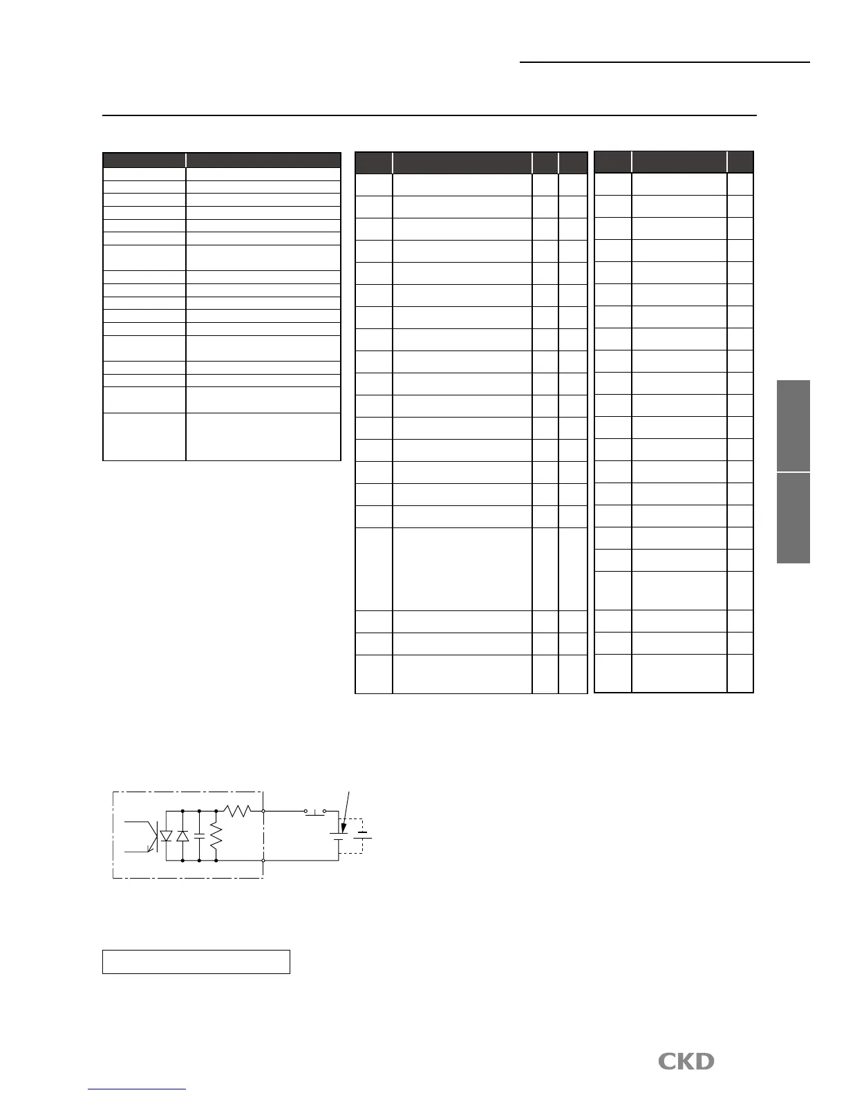
TB3 input circuit specifications (emergency stop)
Maintain sufficient distance between the communication cable and the power and motor cable.
Do not bundle communication and power cable as it may cause communication errors and failures due to
instability caused by noise.
Refer to materials such as CC-Link laying manual for details on laying the cables.
Safety precautions
Device
No.
Signal name
Logic
RXn0 M code output (bit 0)
Positive
RXn1 M code output (bit 1)
Positive
RXn2 M code output (bit 2)
Positive
RXn3 M code output (bit 3)
Positive
RXn4 M code output (bit 4)
Positive
RXn5 M code output (bit 5)
Positive
RXn6 M code output (bit 6)
Positive
RXn7 M code output (bit 7)
Positive
RXn8 Inposition input
Positive
RXn9
Positioning complete
output
Positive
RXnA
Start input waiting
output
Positive
RXnB Alarm output 1
Negative
RXnC Alarm output 2
Negative
RXnD
Output during indexing 1
/origin position output
Positive
RXnE
Output during indexing 2
/servo state output
Positive
RXnF Ready output
Positive
RX(n+1)0
Output
Positive
RX(n+1)1
M code strobe output
Positive
RX(n+1)2
to
RX(n+1)F
Not available
RX(n+2)0
Monitor medium
Positive
RX(n+2)1
Command completion
Positive
RX(n+2)2
to
RX(n+2)F
Not available
CC-Link Specifications
PLC
→
AX(Input)
AX
→
PLC(Output)
 Loading...