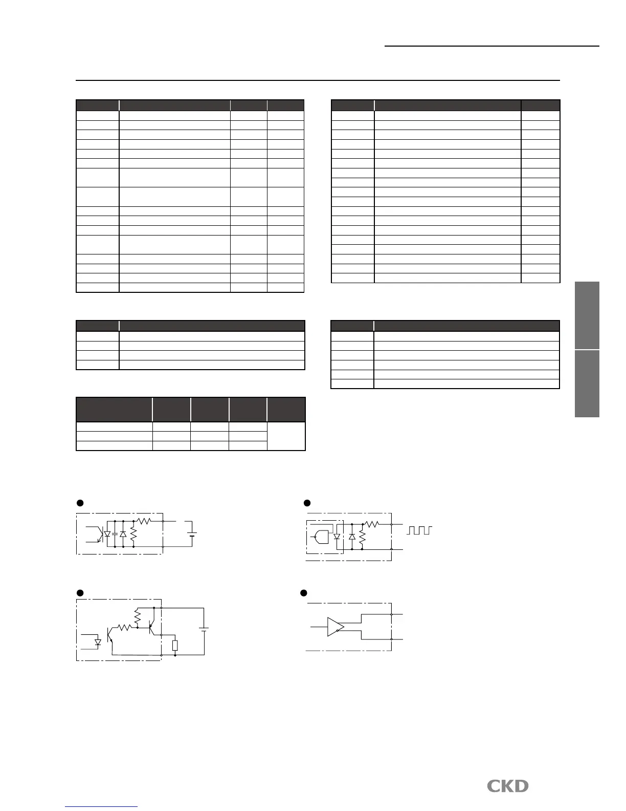
CN3 I/O circuit specifications
I/O circuit specifications
Descriptions
1 circuit
current
(mA)
Max.
point
(Circuit)
Max.
current
(mA)
Max. current
consumption
(mA)
Input circuit 4 14 56
1106Output circuit 50 18 900
Brake output (BK +, BK-)
75 2 150
*The output circuit can only output 14 points out of 18 points
simultaneously.
CN3 output signal
Pin No. Signal name Logic
33 M code output (bit 0) Positive
34
M code output (bit 1) Positive
35
M code output (bit 2) Positive
36 M code output (bit 3)
Positive
37
M code output (bit 4) Positive
38
M code output (bit 5) Positive
39
M code output (bit 6) Positive
40 M code output (bit 7) Positive
41 Inposition input Positive
42 Positioning complete output Positive
43
Start input waiting output Positive
44 Alarm output 1 Negative
45 Alarm output 2 Negative
46
Output during indexing 1/origin position output
Positive
47 Output during indexing 2/servo state output Positive
48 Ready output Positive
49 Output Positive
50 M code strobe output Positive
CN3 input signal
Pin No. Signal name Logic
Judgment
1 to 2 External power input + 24V±10%
3 to 4
External power input GND
5 Program no. selection input (bit 0) Positive Level
6 Program no. selection input (bit 1) Positive Level
7 Program no. selection input (bit 2) Positive Level
8 Program no. selection input (bit 3) Positive Level
9
Program no. setting input 2nd digit/
program no. selection input (bit 4)
Positive
Edge
Level
10
Program no. setting input 1st digit/
program no. selection input (bit 5)
Positive
Edge
Level
11 Reset input Positive Edge
12 Return to origin command input Positive Edge
13
Start input Positive Edge
14
Servo on input/program stop
input
Positive
Level
Edge
15
Ready return/continuous rotation stop input
Positive Edge
16
Answer input/position deviation count reset input
Positive Edge
17 Emergency stop input Negative Level
18 Brake release input Positive Level
CN3 pulse string input signal
Pin No. Signal name
19 PULSE/UP/A phase
20 -PULSE/-UP/-A phase
21 DIR/DOWN/B phase
22 -DIR/-DOWN/-B phase
CN3 encoder output signal (
incremental)
Pin No. Signal name
23 A phase (line driver output)
24 -A phase (line driver output)
25 B phase (line driver output)
26 -B phase (line driver output)
27 Z phase (line driver output)
28 -Z phase (line driver output)
 Loading...