This document serves as an instruction manual for the CKD Block Manifold MN4E0 Series, specifically focusing on the Serial Transmission Slave Unit N4E0-T7EC, which is EtherCAT compatible. It provides essential information for safe and proper use, handling, and maintenance of the product.
Function Description
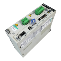
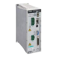
The N4E0-T7EC is a slave unit designed for the N4E0 series, enabling connection to EtherCAT, an open Ethernet network system. It acts as an output device, receiving process data objects (PDO) from a master unit and transmitting them to the manifold solenoid valves. This unit facilitates high-speed communication within an industrial automation network, leveraging the EtherCAT Slave Controller for efficient data exchange. The system primarily consists of a PLC, a master unit, the N4E0-T7EC mounted manifold solenoid valve, and other peripheral EtherCAT slave units.
Usage Features
The N4E0-T7EC slave unit offers several features to enhance usability and integration into industrial systems:
- Simplified Wiring: It connects to a PLC using only a network cable (Category 5 or higher), significantly reducing wiring man-hours compared to traditional systems.
- Separated Power Supplies: The unit power and valve power are separated, which simplifies maintenance procedures and enhances system reliability.
- Flexible Address Setting: The slave unit's address can be configured either through a hard switch on the unit itself or by writing the address from the PLC, offering versatility in system setup.
- Output Point Options: Available in +COM specification with either 16 or 32 output points, making it suitable for a wide range of applications and system sizes.
- Configurable Connector Extraction: Users can select the extraction direction for both the power connector and communication connector, allowing for flexible installation in various physical layouts.
- EtherCAT Compatibility: The unit is designed for EtherCAT networks, which utilize an EtherCAT Slave Controller for super-high-speed communication, distinguishing it from conventional Ethernet. EtherCAT specifications are standardized across several international standards (IEC 61158, IEC 61784, IEC 61800, ISO 15745) and a SEMI standard (E54.20), ensuring broad compatibility and reliability.
- Communication Error Handling: The unit allows users to define the action taken on outputs in the event of a communication error (e.g., disconnection or time-out). Outputs can be set to either "Hold mode" (maintain current status) or "Clear mode" (turn off all outputs). This setting is configured via a slide switch on the unit.
- Node Address Setting: The slave unit node address (ID) is set using a rotary switch, with the upper digit configured by x16 and the lower digit by x1. The factory default is "00," which allows the master unit to assign the node address.
- ESI File Integration: For an EtherCAT device to participate in the network, it must be registered using an ESI (EtherCAT Slave Information) file, which contains the device's communication specifications. The N4E0-T7EC uses the CKD_OPP6.xml file, which supports four models (T7EC1, T7EC2, T7ECT1, T7ECT2) with varying I/O points and output types. Proper registration of the ESI file ensures a suitable network configuration.
- Output Data Mapping: The master unit handles the N4E0-T7EC as a slave device, with PDO output data sent from the master unit to the slave device. The unit receives output data and transmits it to the valves. The manual provides tables for I/O mapping to assist in programming.
- Valve Number Array Correspondence: The manual illustrates how valve numbers correspond to the T7EC solenoid output numbers, clarifying the relationship between station numbers and solenoid types (a-side or b-side). Manifold stations are numbered from left to right, facing the piping port.
Maintenance Features
The manual emphasizes the importance of proper maintenance for the N4E0-T7EC to ensure its longevity and reliable operation:
- Safety First: Before any maintenance, it is crucial to confirm the safety of the entire system, turn off all energy sources (air/water supply, power), and release compressed air. Extreme care must be taken to avoid water or electrical leakage, as hot or live parts may still be present even after operation stops.
- Pre-Maintenance Checks: Before handling, piping, or removing devices, users must confirm system safety. When starting or restarting a machine with pneumatic components, safety measures like pop-out prevention mechanisms should be in place.
- Static Electricity Precautions: Workers are advised to discharge static electricity from their bodies by touching a grounded metal object before handling the EtherCAT device to prevent damage.
- Power-Off Requirement for Settings: Switches for node address and output mode settings must be adjusted only when the unit power is turned off, as changes made while power is on will not be recognized.
- Protection of Internal Components: The cover of the serial transmission slave unit should remain closed except during switch settings to prevent damage or entry of foreign matter, which could lead to unexpected failures. Users are also cautioned against touching the internal circuit board.
- Cable Handling: Power and network cables must be wired properly within specifications, avoiding tension or shocks. Long wiring runs should be secured to prevent damage to connectors or devices.
- Noise Prevention: When wiring, specific measures should be taken to prevent problems caused by noise, such as preparing independent power for each manifold solenoid valve, keeping power cables as short as possible, separating power cables from noise-generating devices (e.g., inverter motors), and keeping network cables away from other power lines.
- Secure Connections: All cables and plugs must be securely connected before turning on power. The power plug flange and wiring screws require specific tightening torques (0.25 N·m for wiring screws, 0.2 to 0.25 N·m for power plug, 0.4 N·m for network plug) to ensure reliable connections.
- No Unauthorized Modifications: Disassembly, modification, or repair of the product is prohibited to prevent failures or malfunctions.
- Protection from Physical Damage: The product should not be dropped or subjected to excessive vibrations or shocks, as its internal parts are made to precise specifications.
- Plug Management: Plugs should not be attached or detached while power is on to avoid failures or malfunctions. Plug fixing screws must be fully loosened before removal and securely tightened after insertion.
- Environmental Considerations: To prevent mold or rust, the product should be stored in a sealed package with desiccant if the shipping environment reaches high temperatures. It should also be kept at least 200 mm away from high-voltage and power lines, or these lines should be wired in grounded metal tubing.
- Daily and Periodic Inspections: Regular cleaning and inspection are recommended for optimum performance. Daily cleaning involves wiping with a soft, dry cloth, or a cloth soaked in diluted neutral detergent for stains. Periodic inspections (once or twice a year, more frequently in harsh environments) include checking surrounding temperature and humidity, dust presence, secure unit fixation, and proper insertion/condition of power and network cables.
- Troubleshooting Guide: The manual provides a troubleshooting section with common issues and their solutions, such as LEDs not lighting up (PW, PW(V), RUN, ERR, INFO), and unexpected output behavior. This includes checking power connections, network cable integrity, ESI file correctness, product name configuration, and node address settings.
- Replacement Procedures: Instructions are provided for removing and mounting the slave unit, emphasizing safety steps like turning off power and confirming secure connections. When replacing a unit, users must ensure the new unit has no abnormalities and that its switch settings match those of the previous unit.