Do you have a question about the Claas QUADRANT 5300 and is the answer not in the manual?
Position piston at top dead center using flywheel and align identification marks on crank wheel.
Pivot knotter for maintenance; adjust clearance between pinion and disk (0.05-0.2mm).
Adjust knotter nose spring (33±1mm) and twine pincer flange spring (28±1mm), check roller contact.
Adjust roller using eccentric shaft for zero clearance with excrescent part; lever must contact pin.
Adjust ball joints on drive shaft to capture clearance, ensuring no displacement of twine guide finger.
Launch tying manually, align wheel axis, measure needle height (X=8±1mm), and adjust needle position.
Align round tie rods and cranks for top dead center needles; adjust tie rod lengths based on twine pincer flange measurement.
Ensure needles are parallel to knotter bodies, check needle guides for clearance (A=0.3±0.2mm).
Adjust clearance (B=8±1mm) between lever and stop using the ball joint and lock nut on both sides.
Adjust needle equalizer beam springs (27±1mm), needle shaft brake springs (27±1mm), and twine box brake springs (55-1mm).
Check twine tension by measuring distance between twine tension springs and bracket (50±20mm).
Retighten or replace knotter nose spring, check knotter nose tongue shape.
Check twine pincer flange setting, status, and use thicker or regular twine.
Clean/tense tensioner, adjust needle height/brake, check twine routing.
Check guidance horn status, twine guide finger adjustment, knotter flange status.
Check knotter nose/tongue, knotter flange, use thicker twine, check guidance horn.
Check pincer flange roller setting, use regular twine, reduce baling pressure.
Check pinion/disk clearance, knotter nose spring tension, pincer flange wheel status.
Reduce baling pressure, adjust pincer flange spring, use recommended twine.
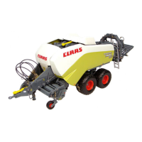
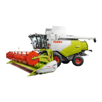
The CLAAS Quadrant 5300 is a large square baler designed for efficient and reliable hay and forage baling. Its primary function is to compress harvested crops into dense, rectangular bales, which are then tied with twine for easy handling, storage, and transport. The machine is engineered to produce consistent bale quality, crucial for preserving the nutritional value of the feed and optimizing storage space.
The core function of the Quadrant 5300 revolves around its tying system, which is critical for securing the bales. The baler operates by feeding crop material into a compression chamber where a piston repeatedly compacts it. Once a predetermined bale length is achieved, a set of needles and knotters engage to tie the bale. The tying process involves several synchronized steps: the needles carry the twine around the bale, the knotters form and secure the knots, and the twine is then cut. This intricate process ensures that each bale is tightly bound and maintains its structural integrity.
The machine's design emphasizes precision in the tying mechanism to minimize errors and maximize productivity. The main settings for the baler involve positioning the piston at the front dead center, which is crucial for initiating the tying cycle correctly. This alignment ensures that the identification marks on the crank hole and crank wheel are properly centered, allowing for accurate synchronization of the baling components. If the driveshaft position needs adjustment, it can be repositioned to optimize the piston's movement and the overall baling operation.
The Quadrant 5300 offers several usage features designed to facilitate operation and maintenance, particularly concerning the knotter and needle settings.
The knotters are the heart of the tying system, and their precise adjustment is paramount.
The needles carry the twine around the bale, and their height and alignment are crucial for proper tying.
The Quadrant 5300 incorporates features that simplify maintenance and troubleshooting, ensuring the baler remains in optimal working condition.
The manual provides a comprehensive troubleshooting guide for common tying problems, linking specific symptoms to their causes and solutions. This guide is a key maintenance feature, allowing operators to diagnose and rectify issues efficiently.
This detailed guidance allows operators to systematically address tying errors, ensuring the baler consistently produces high-quality bales. The emphasis on regular checks and adjustments, especially when arriving in the field, underscores the importance of proactive maintenance for optimal performance.
| Model | QUADRANT 5300 |
|---|---|
| Bale Size | 120 x 90 cm |
| Number of Knotters | 6 |
| Bale chamber width | 1.20 m |
| Bale Weight | up to 500 kg |
| Bale chamber height | 90 cm |
| Engine Power | 160 HP |