WS1.5", 2" and 2"QC Drawings and Service Manual Page 33
** V3010-2X-15X Injectors contain a V3010-2-15 WS2 injector adapter with a WS1.5 injector inside
V3010-2X injectors and the V3010-2-15 Adapter include a V3283 O-RING 117 and a V3284 O-RING 114. The V3010-2-15 Adapter allows the 2"
valve to be used on smaller tank sizes. The V3010-2-15 adapter can be used with any V3010-15X injector. The V3010-15X injector includes one
V3416 O-RING 012 (lower) and one V3171 O-RING 013 (upper).
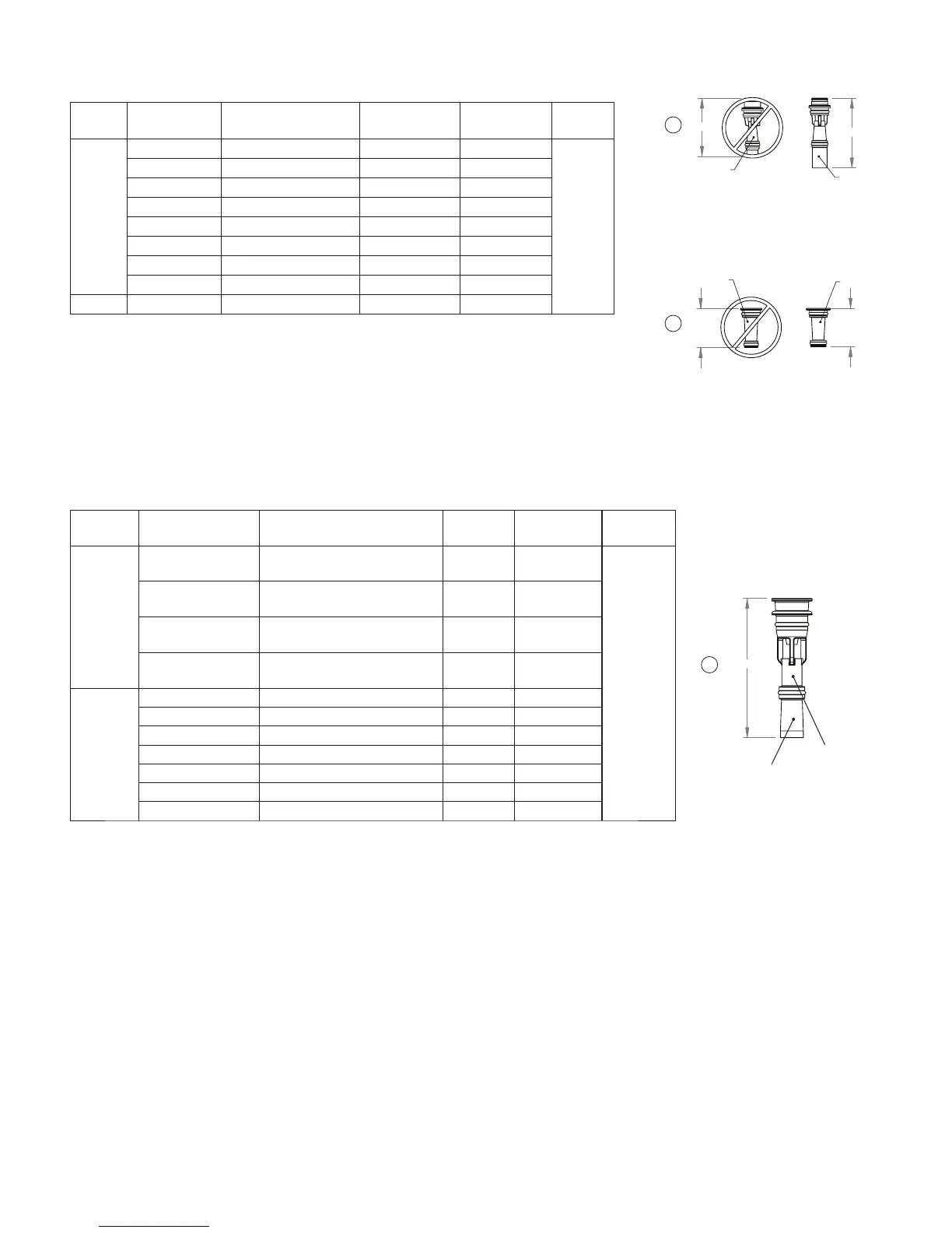
WS 1.5” and 1.5” Gen 2 Injectors
WS 2” and 2” QC Injectors
Drawing
No.
Order No. Description Identifi er
Typical Tank
Diameter
1
Quantity
Not
Shown
V3010-2R-15B **
WS2 / 2H Injector Assembly
R, W/V3010-15B
Violet
12”
1
V3010-2S-15C **
WS2 / 2H Injector Assembly
S, W/V3010-15C
Red
13”
V3010-2T-15D **
WS2 / 2H Injector Assembly
T, W/V3010-15D
White
14”
V3010-2U-15E **
WS2 / 2H Injector Assembly
U, W/V3010-15E
Blue
16”
3
V3010-2A WS2 / 2H Injector Assembly A Stamped A 18”
V3010-2B WS2 / 2H Injector Assembly B Stamped B 21”
V3010-2C WS2 / 2H Injector Assembly C Stamped C 24”
V3010-2D WS2 / 2H Injector Assembly D Stamped D 30”
V3010-2E WS2 / 2H Injector Assembly E Stamped E 36”
V3010-2F WS2 / 2H Injector Assembly F Stamped F 42”
V3010-2G WS2 / 2H Injector Assembly G Stamped G 48”
1. Actual injector size may vary depending on the design and application of the system. The injectors are sized for a typical downfl ow softener
using standard mesh synthetic cation exchange media regenerating with sodium chloride. See the injector graphs on the following pages to meet
specifi c applications. Variances in drain and draw line restrictions will effect injector performance.
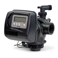
&RORUHG
%ODFN
For WS1 and
WS1.25 valves.
Do not use on
WS1.5 or WS2
valves.
1
2
:6,QMHFWRU
$*
Black
Stamped
Identifi er
3
%ODFN
*UH\
For WS1 and
WS1.25 valves.
Do not use on
WS1.5 or WS2
valves.
Drawing
No.
Order No. Description Nozzle Color
Typical Tank
Diameter
1
Quantity
1
V3010-15B WS1.5 Injector Asy B Violet 12”
1
V3010-15C WS1.5 Injector Asy C Red 13”
V3010-15D WS1.5 Injector Asy D White 14”
V3010-15E WS1.5 Injector Asy E Blue 16”
V3010-15F WS1.5 Injector Asy F Yellow 18”
V3010-15G WS1.5 Injector Asy G Green 21”
V3010-15H WS1.5 Injector Asy H Orange 24”
V3010-15I* WS1.5 Injector Asy I Machined PVC 30”
2 V3010-15Z WS1.5 Injector Plug NA
*Requires a V3158-02 WS1 DRN ELBOW ¾ ASY be installed. Also required is H7070-36CF-5
454CF BRINE VALVE 36 or H7070-54CF-5 454CF BRINE VALVE 54, with 5 GPM brine line fl ow
control, 1” Air Check, or 494 Brine Valve Assembly, with a minimum ¾” hard pipe PVC brine line.
V301015B through V3010-15H injectors include one V3416 o-ring 012 (lower) and one V3171 o-ring
013 (upper).
V3010-15I injector includes two V3171 o-ring 013 and is for use on WS1.5 Gen 2 valves only.
 Loading...