Owner’s Manual
3
Owner’s Manual
DESCRIPTION
The APX201.2 and APX401.2 use an unregulated MOSFET power supply for
superior control of output wattage. A toroid-coil transformer yields maximum
power transfer with minimal heat loss. Extensive attention to circuit design
keeps AM RFI at low levels, so you won’t hear unwanted noise when the level
is cranked up. Protection circuits safeguard the amplifier when overheating,
speaker shorts, or improper load conditions occur.
All connections and controls of the APX201.2 and APX401.2 are on the end
panels and are easy to understand. Gold-plated RCA and barrier connectors
are used to ensure the best electrical connection for your system. Integrated
into the power and speaker end panel is an external automotive type fuse that
is easy to replace.
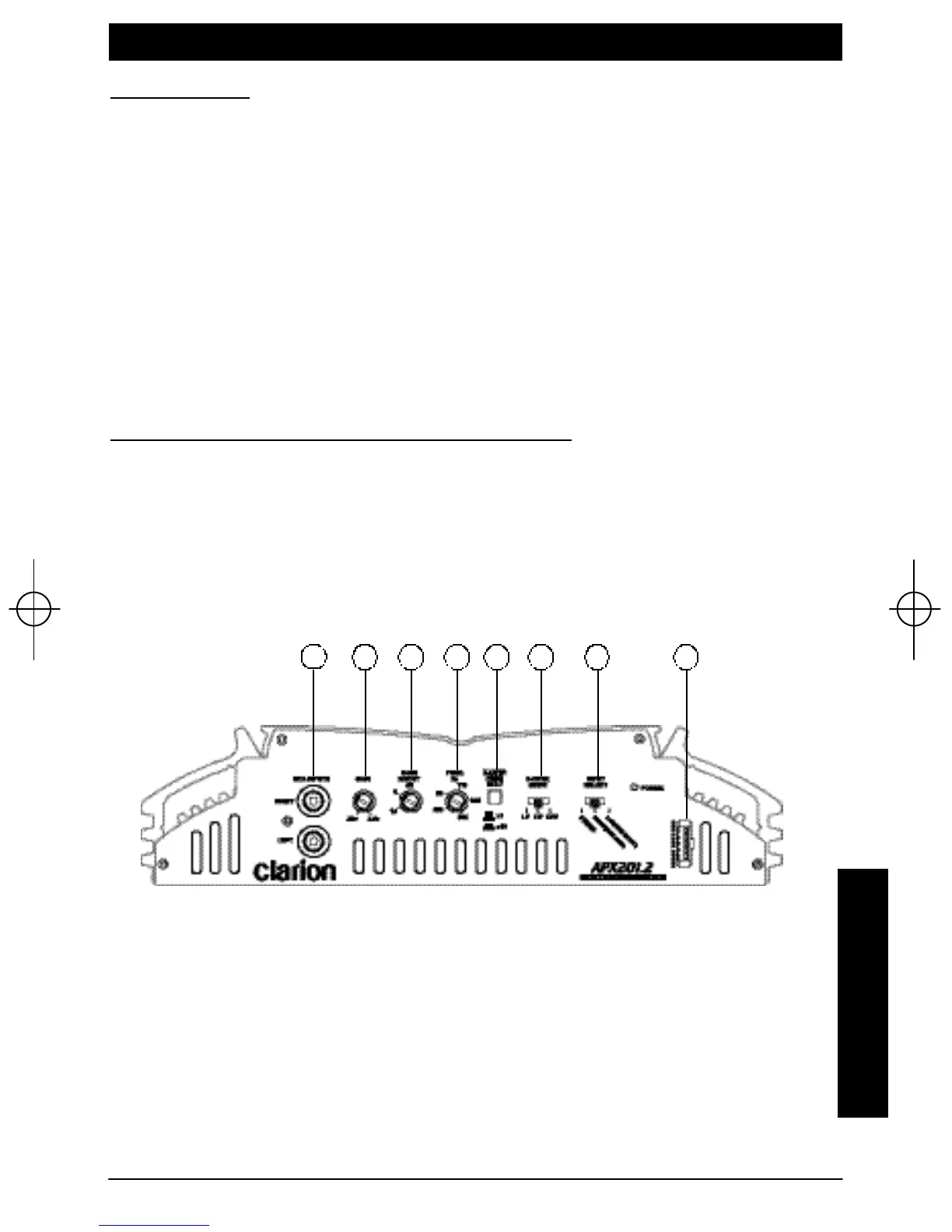
INPUT CONNECTIONS AND AUDIO CONTROLS
The front panel of the APX201.2 and APX401.2 both contain connections for
RCA Inputs or Speaker Level Inputs and Audio Controls as shown below.
The RCA input connections feature gold-plated RCA jacks and are labeled as
RIGHT and LEFT.
1. RCA Input Jacks
2. Gain Control
3. Bass Boost Control
4. Freq (Hz) Selection Control
5. Crossover Frequency Multiplier Switch
6. X-Over Mode Switch
7. Input Select Switch
8. Speaker Level Inputs
Figure 1-
1 2 3 4 5 6 7 8
apx201.qxd 12/5/01 12:57 PM Page 3
 Loading...