- 5 -- 5 -
- 5 -- 5 -
- 5 -
DB345MP/DB346MPDB345MP/DB346MP
DB345MP/DB346MPDB345MP/DB346MP
DB345MP/DB346MP
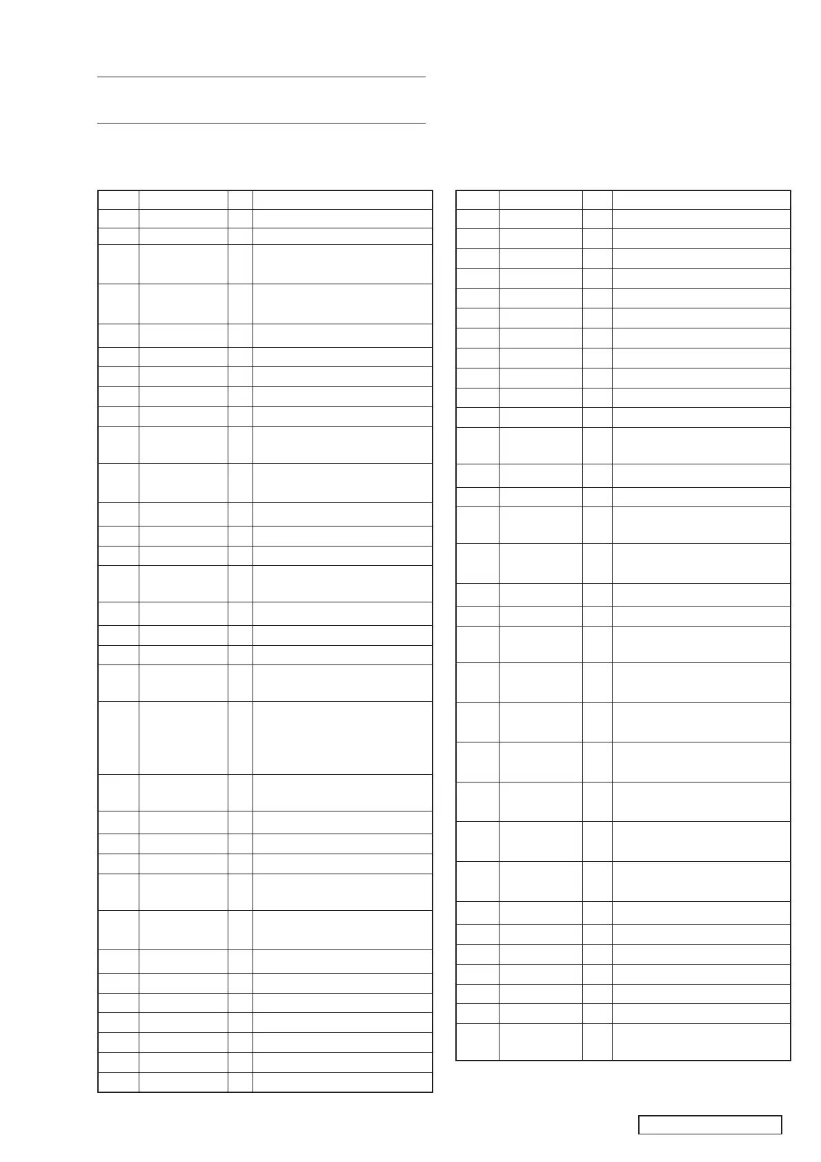
1 VOL_CLK O E-VOL Control Clock output
2 VOL_DATA O E-VOL Control Data output
3 REM_DET I While protecting circuit motion, it
is at ‘HI’
4 OFFSET DET I While Power Amp IC is abnormal,
it is at ‘LOW’
5 PHONE_INT I NC
6NC -NC
7 MP3 REQ I REQ input from MP3 decoder
8NC -NC
9 VDD - Power supply terminal 5V
10 X_OUT - Crystal 12MHz (Main system
clock)
11 X_IN - Crystal 12MHz (Main system
clock)
12 VSS - GND
13 XT_OUT - NC
14 XT_IN - GND
15 RESET - Reset port (When system is
reset, it is at ‘LOW’)
16 NC - NC
17 B/U DET I B/U detecting terminal
18 ACC DET I ACC detecting terminal
19 REMOCON I IR Sensor signal input for Remote
Control
20 KEY_INT I When this terminal turns low, key
A/D terminal detects the key
pushed (FNC, EJECT & DCP
keys)
21 SBSY I GS1-MC CD Sub-code block
sync detection input
22 TBASE I PLL Time Base signal input (8Hz)
23 AVDD - Analog Power supply 5V
24 AVREF0 - ADC Reference Voltage Input
25 KEY A/D I FNC/EJECT/DCP detection
terminal for A/D converter
26 TEST I TEST keys detection terminal
(For Test Mode purpose)
27 NC - NC
28 NC - NC
29 NC - NC
30 NC - NC
31 NC - NC
32 NC - NC
33 AVSS - Analog GND
Terminal Description
34 NC - NC
35 NC - NC
36 AVREF1 - DAC Reference Voltage Input
37 NC - NC
38 NC - NC
39 NC - NC
40 NC - NC
41 NC - NC
42 NC - NC
43 NC - NC
44 NC - NC
45 MP3 SDA I/O MP3 Data Communication Port
(I2C bus)
46 NC - NC
47 MP3 SCL O MP3 Clock Output (I2C bus)
48 MP3 RESET O When MP3 decoder is reset, it is
at ‘LOW’
49 MP3 STANDBY O When MP3 decoder is at standby
mode, it is at ‘LOW’
50 STANDBY O Power Amp IC control terminal
51 REM_ON O While Power on, it is at ‘HI’
52 CD_8V_REM O CD power supply control terminal
+8V
53 B/L + B O Illumination Control Output (While
ACC is ON, it is at ‘HI’)
54 CS1 I Destination Selection Input. Refer
Table 1.
55 CS2 I Destination Selection Input. Refer
Table 1.
56 LCD SI I Serial data input communication
line to LCD Control IC
57 LCD SO O Serial data output communication
line to LCD Control IC
58 LCD SCK O Serial clock output communication
line to LCD Control IC
59 LCD CE O LCD chip enable output
60 VOL-CW I Use for rotary volume
61 VOL-CCW I Use for rotary volume
62 NC - NC
63 NC - NC
64 NC - NC
65 TR-B I GS1-MC CD Disc Detection Input
(HI: with disc, LOW: without disc)
Pin No PIN NAME I/O DESCRIPTIONPin No PIN NAME I/O DESCRIPTION
EXPLANATION OF IC
uPD784215AYGC-129-8EU 052-3933-00
Master Micro computer
Outward FormOutward Form
Outward FormOutward Form
Outward Form
100 pins, plastic QFP

 Loading...