EasyManua.ls Logo

Clarion PU-2471A-G User Manual

Clarion PU-2471A-G
14 pages
To Next Page IconTo Next Page
Page #1 background imageLoading...
Page #1 background image
PU-2471A
PU-2472B, C
- 1 -
Published by Service Dept.
Printed in Japan
Clarion Co., Ltd.
50 Kamitoda, Toda-shi, Saitama 335-8511 Japan
Service Dept.: 5-66 Azuma , Kitamoto-shi, Saitama 364-0007 Japan
Tel: +81-48-541-2335 / 2432 FAX: +81-48-541-2703
298-6067-00
Mar.2003
Service Manual
Model
PEUGEOT/CITROEN
Automobile Genuine
RDS/FM/MW/LW Radio
& CD Stereo Player
PU-2471A-G
PU-2471A-H
PU-2472B-C
PU-2472C-C
Model
Model
Model
PU-2472B-C (WITH DUMMY COVER) / PU-2472C-C
SPECIFICATIONS
LW tuner section
Tuning system: PLL frequency synthesizer system
Receive range: 153kHz to 279kHz
Quieting sensitivity: Less than 43dBu(at 20dB S/N)
Auto tuning stop sensitivity:
35+10/-10dBu(DX)
62+10/-10dBu(LO)
MW tuner section
Tuning system: PLL frequency synthesizer system
Receive range: 531kHz to 1,602kHz
Quieting sensitivity: Less than 36dBu(at 20dB S/N)
Auto tuning stop sensitivity:
35+10/-10dBu(DX)
62+10/-10dBu(LO)
FM tuner section
Tuning system: PLL frequency synthesizer system
Receive range: 87.5MHz to 108.0MHz
Intermediate frequency:
10.7MHz
Quieting sensitivity: Less than 13dBu(at 30dB S/N)
Separation: More than 20dB
Auto tuning stop sensitivity:
21+8/-8dBu(DX)
47+10/-10dBu(LO)
CD player section
Separation: More than 65dB(1kHz)
S/N ratio: More than 80dB(1kHz)
Distortion: Less than 1.0%(1kHz)
General
Audio Power output: More than 10W x 4
Power supply voltage: DC13.5V Negative ground
Current consumption: Less than 10A
Dimensions(mm): 178(W) x 50(H) x 156.6(D)
COMPONENTS
PU-2471A-G,A-H/PU-2472B-C,C-C
Main unit ----------- 1
NOTES
* We cannot supply PWB with component parts in prin-
ciple. When a circuit on PWB has failure, please repair
it by component parts base. Parts which are not men-
tioned in service manual are not supplied.
* Prevent damage caused by static electricity when re-
pairing the pick-up.
The pattern of the pick-up is short-circuiting for preven-
tion. Remove the soldering with a solder iron whose in-
sulation resistance is larger than 10M ohm(DC500V) after
complete connection to the main PWB. For repair table
shall use copper or conductive sheet (with impedance is
lower to 100M ohm from 1M ohm) such as a sheet.
Be sure to put on a wrist-strap for prevent electric static's
Question and Answer IconNeed help?

Do you have a question about the Clarion PU-2471A-G and is the answer not in the manual?

Clarion PU-2471A-G Specifications

General IconGeneral
CategoryCar Receiver
ModelPU-2471A-G
BrandClarion
TypeCD Receiver
Radio TunerAM/FM
CD PlayerYes
BluetoothNo
Channels4
EqualizerYes
Frequency Response20 Hz - 20 kHz
Supported formatsMP3, WMA

Summary

Specifications and Components

Tuner Sections Specifications

Details of LW, MW, and FM tuner performance and tuning systems.

CD Player and General Specifications

Specifications for the CD player section and general operational parameters.

Main Unit Component Identification

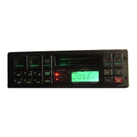
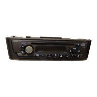
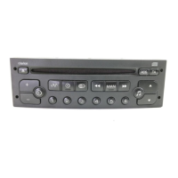
Identification of the main unit component within the system.

Important Repair and Handling Notes

Critical notes on PWB repair, static electricity, and pick-up handling.

Engineer and Repair Cautions

General Repair Guidelines

Essential instructions for safe and correct product repair procedures.

Static Electricity and Handling Precautions

Specific warnings and procedures for handling sensitive components.

Laser Product Safety Information

Information regarding the product's Class 1 Laser Product classification.

IC Terminal Explanations

CD & Radio System Controller Pinout

Detailed pin descriptions for the uPD784216BYGC-110-8EU IC.

Exploded View and Parts Lists

Main Section PU-2471A Parts

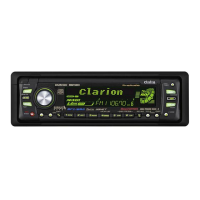
Diagram and itemized list of parts for the PU-2471A main unit.

Main Section PU-2472B,C Parts

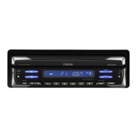
Diagram and itemized list of parts for the PU-2472B,C main units.

CD Mechanism Diagram

Exploded view of the CD mechanism (929-0220-80) showing component layout.

Electrical Parts Lists by PWB

Main PWB Components (B1)

Detailed list of electrical parts for the Main PWB (B1).

Switch PWB Components (B2)

List of electrical parts for the Switch PWB (B2).

ISO PWB Components (B3)

List of electrical parts for the ISO PWB (B3).

CD PWB Components (B4)

List of electrical parts for the CD PWB (B4).

Printed Wiring Board Layouts

Switch PWB (B2) Layouts

Printed wiring board layout for Switch PWB sections PU-2471A and PU-2472B/C.

Circuit Diagrams by Section

ISO PWB Circuit Diagram

Circuit diagram for the ISO PWB section (B3).

Switch PWB Circuit Diagrams

Circuit diagrams for Switch PWB sections PU-2471A and PU-2472B/C.

CD PWB / LED PWB Circuit Diagram

Circuit diagram for CD PWB (B4) and LED PWB (B5).

Related product manuals