7
Parts & Service: 020 8988 7400 / E-mail: Parts@clarkeinternational.com or Service@clarkeinternational.com
ARC WELDING
A consumable electrode is connected to a high ampage low voltage supply
which creates an electric arc between the electrode and the workpiece.
NOTE: When using the welder outside, you may need to take measures
to erect a wind break to make sure the shielding gas is not blown
away, thereby leaving a poor quality weld.
PREPARATION
• Arc welding cables are supplied with this machine.
To prepare the unit for ARC welding, it is important that you follow the
procedure below.
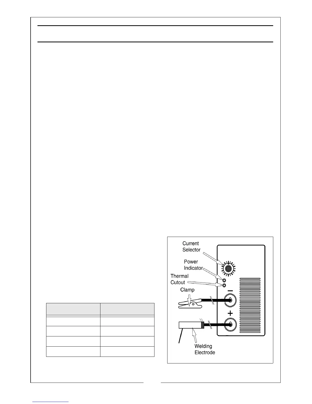
1. Making sure that the ON/OFF switch, located on the rear panel is in the OFF
position, connect the welding leads as follows:
• Welding rod holder lead to the +ve terminal.
• Work clamp lead to the -ve terminal.
2. Select the appropriate welding rod and insert it into the welding rod holder.
• The size (diameter) of the welding rod should be approximately the
same as the thickness of metal to be welded.
3. Attach the work clamp to the workpiece as close as possible to the area
being welded. Clean with a wire brush where necessary to ensure the
connection is as clean as possible.
4. Set the required current using the
current selector.
• With practice you will gain a feel
for the correct current setting for
different welding rod thicknesses.
• The following table gives a useful
guideline.
Welding Rod Size Current (Amps)
1.5 mm 30-40
2.0 mm 50 - 65
2.5 mm 70 - 100
3.0 mm 100 - 125