K
Kyle HendersonAug 14, 2025
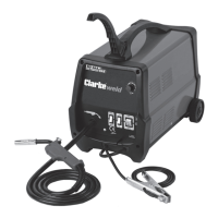
Why does my Clarke MIG 100E produce poor quality welds?
- KKelly FloresAug 14, 2025
Poor quality welds with the Clarke Welding System can result from several factors. First, ensure sufficient gas is reaching the weld area and that drafts aren't blowing it away; increase the gas supply if needed. Second, verify you're using the correct gas and wire combination, consulting your MIG welding manual for the proper setup. Also, the workpiece should be clean and dry, free from rust, paint, dampness, oil, or grease. The wire should also be clean and dry. Finally, check the earth clamp and workpiece connection to ensure good contact.