Parts Diag
A wide range of accessories is available from your nearest CLARKE dealer, for further
information, contact your nearest dealer, or telephone CLARKE International Sales de-
partment on 01992 565300.
-13-
-6-
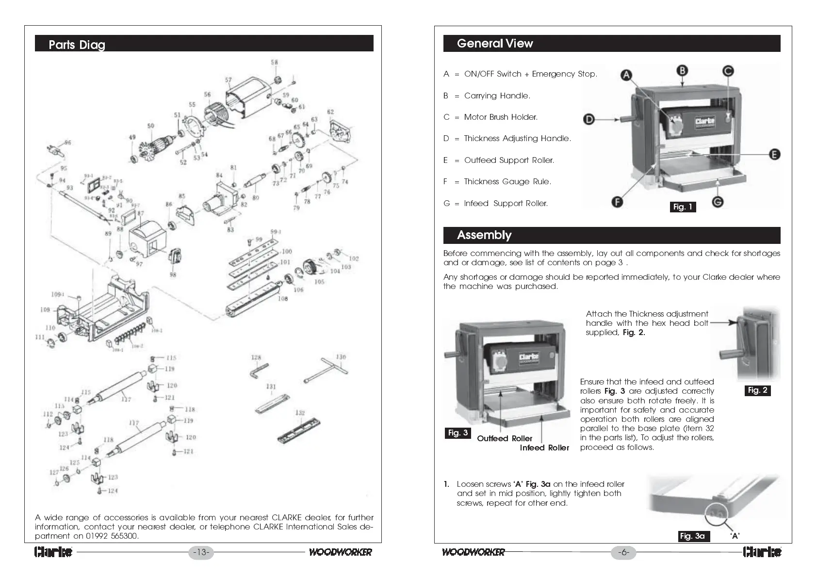
General View
Assembly
Before commencing with the assembly, lay out all components and check for shortages
and or damage, see list of contents on page 3 .
Any shortages or damage should be reported immediately, to your Clarke dealer where
the machine was purchased.
Fig. 1
A = ON/OFF Switch + Emergency Stop.
B = Carrying Handle.
C = Motor Brush Holder.
D = Thickness Adjusting Handle.
E = Outfeed Support Roller.
F = Thickness Gauge Rule.
G = Infeed Support Roller.
Fig. 2
Fig. 3
Infeed Roller
Outfeed Roller
Attach the Thickness adjustment
handle with the hex head bolt
supplied,
Fig. 2.
Ensure that the infeed and outfeed
rollers
Fig. 3
are adjusted correctly
also ensure both rotate freely. It is
important for safety and accurate
operation both rollers are aligned
parallel to the base plate (item 32
in the parts list), To adjust the rollers,
proceed as follows.
1.
Loosen screws
A Fig. 3a
on the infeed roller
and set in mid position, lightly tighten both
screws, repeat for other end.
FFig.
A
Fig. 3a
AAAAA
 Loading...