Maintenance
Before carrying out any cleaning or maintenance activities, ALWAYS ensure the
machine is switched OFF and isolated from the main electrical supply by removing the
plug from the socket.
Clean the machine regularly and inspect for signs of wear and or damage, any defects
should be rectified before using the machine again.
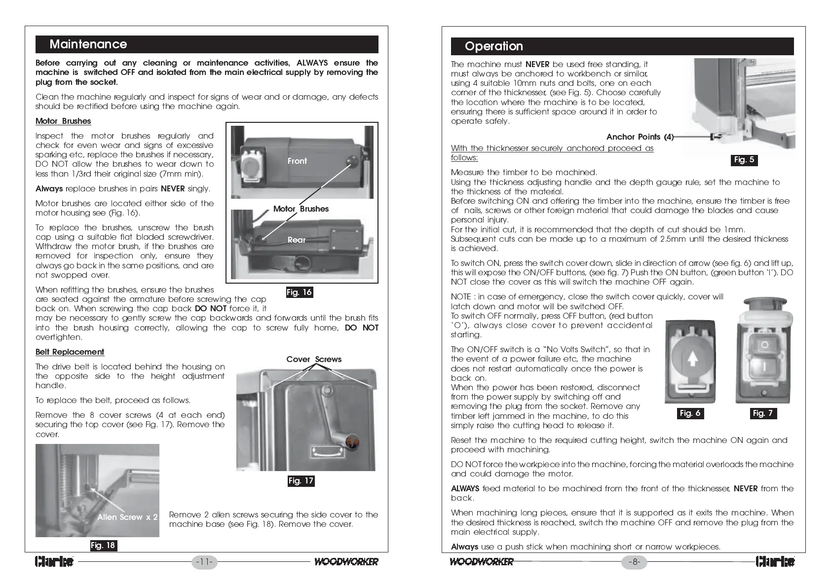
Motor Brushes
Inspect the motor brushes regularly and
check for even wear and signs of excessive
sparking etc, replace the brushes if necessary,
DO NOT allow the brushes to wear down to
less than 1/3rd their original size (7mm min).
Always
replace brushes in pairs
NEVER
singly.
Motor brushes are located either side of the
motor housing see (Fig. 16).
To replace the brushes, unscrew the brush
cap using a suitable flat bladed screwdriver.
Withdraw the motor brush, if the brushes are
removed for inspection only, ensure they
always go back in the same positions, and are
not swopped over.
When refitting the brushes, ensure the brushes
are seated against the armature before screwing the cap
back on. When screwing the cap back
DO NOT
force it, it
may be necessary to gently screw the cap backwards and forwards until the brush fits
into the brush housing correctly, allowing the cap to screw fully home,
DO NOT
overtighten.
Belt Replacement
The drive belt is located behind the housing on
the opposite side to the height adjustment
handle.
To replace the belt, proceed as follows.
Remove the 8 cover screws (4 at each end)
securing the top cover (see Fig. 17). Remove the
cover.
Remove 2 allen screws securing the side cover to the
machine base (see Fig. 18). Remove the cover.
Front
Rear
Motor Brushes
Fig. 16
Cover Screws
Fig. 17
Fig. 18
Allen Screw x 2
-11-
-8-
Operation
The machine must
NEVER
be used free standing, it
must always be anchored to workbench or similar,
using 4 suitable 10mm nuts and bolts, one on each
corner of the thicknesser, (see Fig. 5). Choose carefully
the location where the machine is to be located,
ensuring there is sufficient space around it in order to
operate safely.
With the thicknesser securely anchored proceed as
follows:
Measure the timber to be machined.
Using the thickness adjusting handle and the depth gauge rule, set the machine to
the thickness of the material.
Before switching ON and offering the timber into the machine, ensure the timber is free
of nails, screws or other foreign material that could damage the blades and cause
personal injury.
For the initial cut, it is recommended that the depth of cut should be 1mm.
Subsequent cuts can be made up to a maximum of 2.5mm until the desired thickness
is achieved.
To switch ON, press the switch cover down, slide in dir ection of arrow (see fig. 6) and lift up,
this will expose the ON/OFF buttons, (see fig. 7) Push the ON button, (green button I). DO
NOT close the cover as this will switch the machine OFF again.
NOTE : in case of emergency, close the switch cover quickly, cover will
latch down and motor will be switched OFF.
To switch OFF normally, press OFF button, (red button
O), always close cover to prevent accidental
starting.
The ON/OFF switch is a No Volts Switch, so that in
the event of a power failure etc, the machine
does not restart automatically once the power is
back on.
When the power has been restored, disconnect
from the power supply by switching off and
removing the plug from the socket. Remove any
timber left jammed in the machine, to do this
simply raise the cutting head to release it.
Reset the machine to the required cutting height, switch the machine ON again and
proceed with machining.
DO NOT force the workpiece into the machine, forcing the material overloads the machine
and could damage the motor.
ALWAYS
feed material to be machined from the front of the thicknesser,
NEVER
from the
back.
When machining long pieces, ensure that it is supported as it exits the machine. When
the desired thickness is reached, switch the machine OFF and remove the plug from the
main electrical supply.
Always
use a push stick when machining short or narrow workpieces.
Fig. 5
Fig. 6
Fig. 7
Anchor Points (4)
 Loading...