Page 39 of 49
• Alarm 2: Low Oil Pressure: DP, DQ, DR, DS:
With the engine running, jumper the engine mounted
low oil pressure switch at terminal “WK” to
“GROUND”. DT only: With the engine
running, jumper the engine mounted Low Oil
Pressure switch (see Figures #33A, 33B, 34 for
location).
Wait for 15 seconds and controller alarm will
activate.
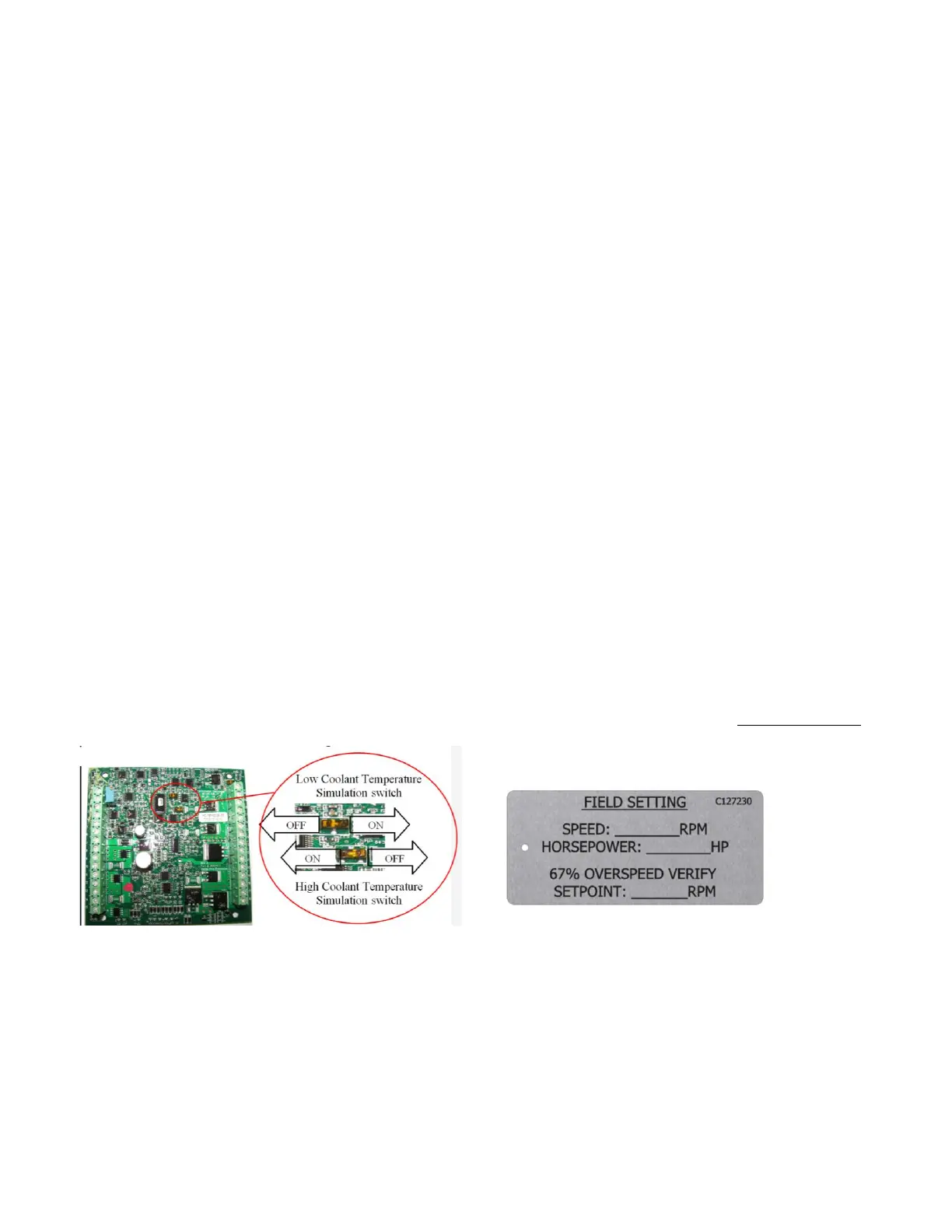
• Alarm 3: High Engine Coolant Temperature:
With the engine running, set the High Engine Coolant
Temperature DIP switch to “ON” (see Figure #36).
Use a fine pick or small screwdriver and slide the
white slider to the left. Wait for 30 seconds and
controller alarm will activate. Set white DIP switch
slider to “OFF” (right) when simulation is complete.
• Alarm 4: Low Engine Coolant Temperature: With
the engine not running, set the Low Engine Coolant
Temperature DIP switch to “ON” (see Figure #36).
Use a fine pick or small screwdriver and slide the
white slider to the right. Controller alarm will
activate immediately. Set white DIP switch slider to
“OFF” (left) when simulation is complete.
• Alarm 5: Overcrank: Use manual stop override
(ETS Governor Solenoid) to prevent the engine from
starting during the cycle-crank testing. NEVER shut
off the fuel supply to the engine to prevent it from
starting. Shutting off the fuel supply will
cause an air lock condition in the fuel system
and possibly cause fuel system component
damage.
Figure #36
3.5.7 BATTERY REQUIREMENTS
All Clarke engine models require 8D batteries, as
sized per SAE J537 and NFPA20. The battery
should meet the following criteria:
Cold Cranking Amps (CCA @ 0°F): 1400
Reserve Capacity (minutes): 430
Refer to Clarke drawing (see Page 5) for
additional information on Clarke supplied
batteries.
3.6 ENGINE SPEED ADJUSTMENT
A mechanical governor controls the engine speed.
The governor is built into the fuel injection pump. All
governors are adjusted to the rated speed at
nameplate power or maximum allowed pump load
before leaving Clarke. During Start-Up Inspection or
when placing reconditioned units into service, some
minor speed adjustment may be required. It is
recommended that this adjustment be performed by
the authorized Service Dealer representative.
To adjust the speed of the engine:
A. Start the engine by following the “To Start
Engine” Procedure in this manual.
B. Let the engine warm-up. Loosen the jam
nut(s) (Figure #37B, C, D).
C. While observing the instrument panel tach
rotate the long adjustor clockwise to lower
the RPM and counter clockwise to raise the
RPM’s until desired speed is obtained. Ref.
Figure #37B, C, D.
D. Holding secure the long adjustor with a
wrench tighten the jam nut.
E. Stop engine by following “To Stop Engine”
Procedure in this manual.
If the engine has been designed and tested for range
rating, stamp the metal tag titled “FIELD SETTING”
with the final adjusted speed, horsepower, and 67%
overspeed verify shutdown setting and keep with the
engine. Refer to Figure #38A.
Figure #38A
 Loading...