6
Lifting Point
Automatic Start
Rotating Parts
Space Heater Voltage
Air Filter Installation
2.0 INSTALLATION/OPERATION
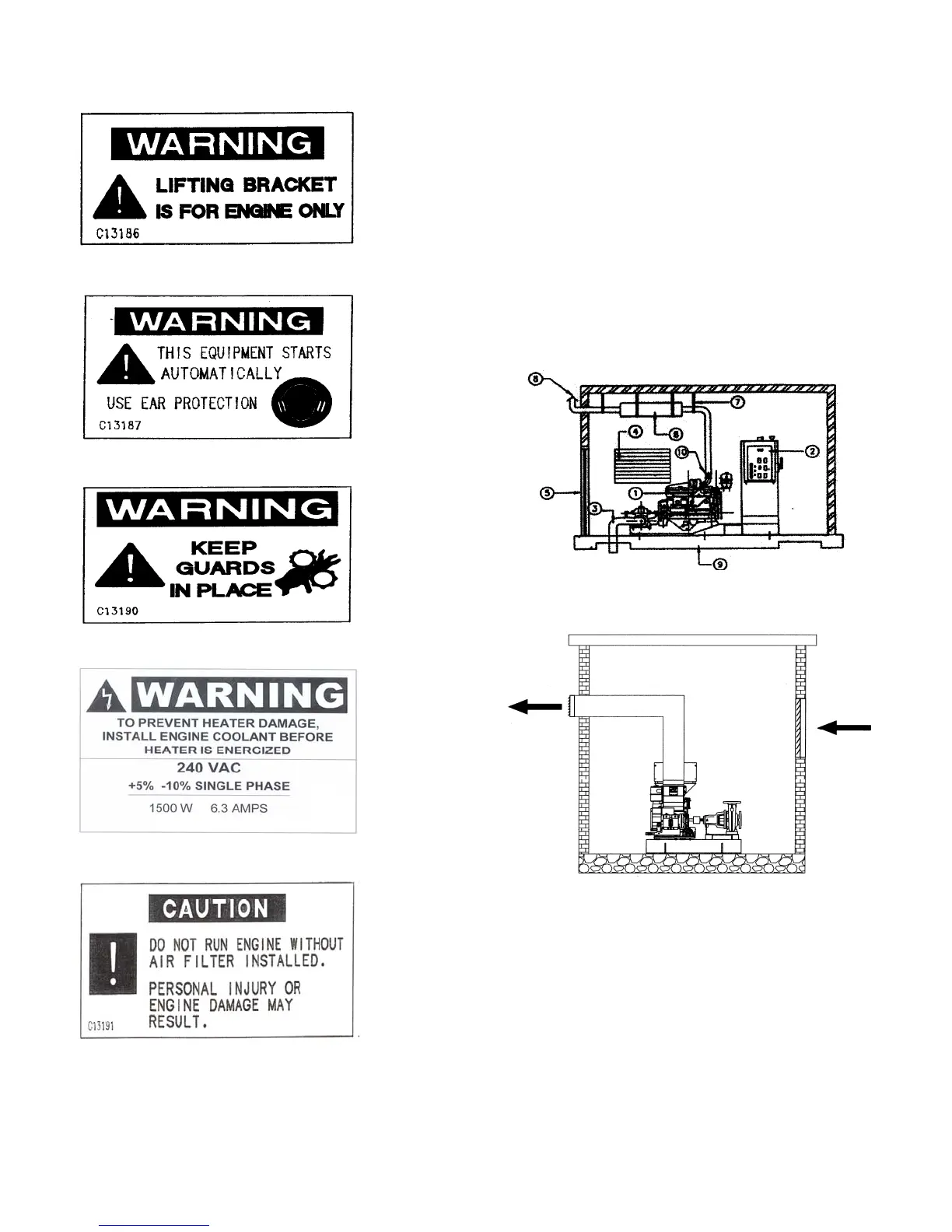
2.1 TYPICAL INSTALLATION
A typical Fire Pump installation is shown in Figure
#6 & 6A.
1. Pump/Engine set
2. Main Pump Controller
3. Pump discharge
4. Air louver
5. Entrance door with air louver
6. Exhaust silencer
7. Exhaust system supports
8. Exhaust outlet pipe
9. Concrete base
10. Exhaust flexible connection joint/pipe
11. Air Discharge Duct
Figure #6
Typical Installation
Figure #6A
Typical Installation
2.2 ENGINE STORAGE
2.2.1 Storage less than 1 year
Storing engines requires special attention. Clarke
engines, as prepared for shipment, may be stored for
a minimum of one year. During this period, they
should be stored indoors in a dry environment.
Protective coverings are recommended provided they
are arranged to allow for air circulation. The stored
engine should be inspected periodically for obvious
conditions such as standing water, part theft, excess