13
Parts & Service: 020 8988 7400 / E-mail: Parts@clarkeinternational.com or Service@clarkeinternational.com
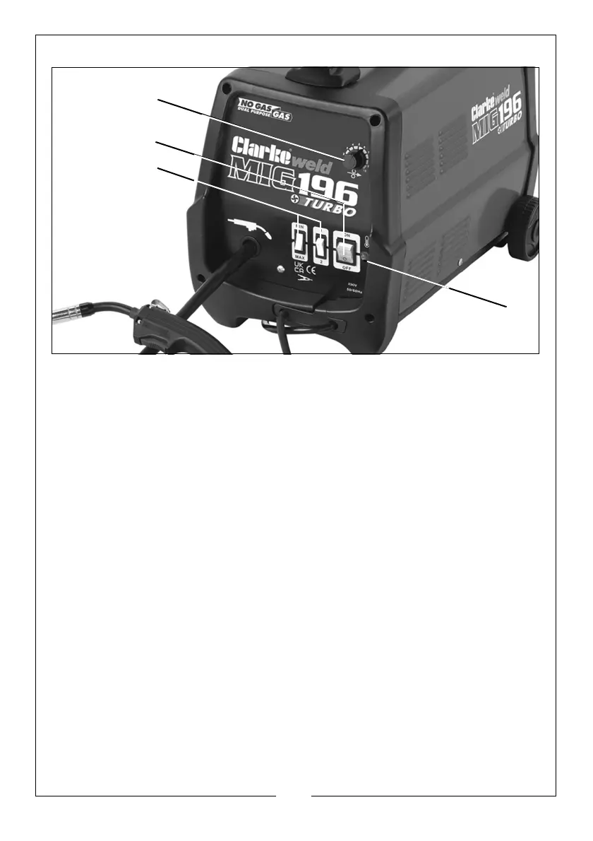
THE CONTROL PANEL
1. Thermal overload light. If the duty cycle is exceeded as a result of welding
too long with a high current, the yellow overload light will illuminate and the
welder will turn off. When the welder has cooled down (approx. 5 to 10
minutes), the power will be restored and welding can recommence.
2. Power ON/OFF switch. When the power is ON the green switch will be
illuminated. When the welder is no longer required, the Power On/Off switch
should be switched to the OFF position and the plug should be disconnected
from the mains supply.
3. Current setting switches MIN-MAX & 1-2. Used together these two switches
provide 4 increasing power levels as follows:
•MIN-1
•MIN-2
•MAX-1
• MAX-2.
4. Wire speed control knob. As a general rule, a higher current requires a
higher wire speed.
 Loading...