18
Parts & Service: 020 8988 7400 / E-mail: Parts@clarkeinternational.com or Service@clarkeinternational.com
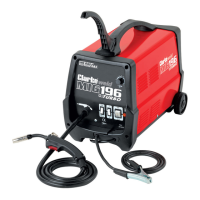
4. Pass the wire through the guide,
over the drive roller and into the
torch liner.
• Push about 10-15 cm into the
torch liner.
5. Lower the arm and replace the
tensioning knob.
• Tighten the tensioning knob
sufficiently to hold firmly, but do
not fully tighten.
NOTE: Correct tension will allow the wire to feed into the torch liner
smoothly, but will allow the drive roller to slip in the event of a
blockage.
6. Close the side panel of the
welder.
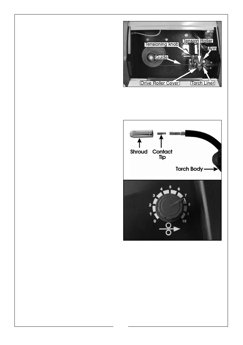
7. Pull off the torch shroud with a
twisting movement, then unscrew
the contact tip.
8. Connect the welder to the power
supply and switch ON.
9. Set the ‘WIRE FEED’ rotary control
on the front panel to position 7 or
8 and squeeze the trigger on the
torch body.
• The wire will feed through the
hose until it appears at the
torch tip.
• Ensuring the hose is free from
kinks during this process will
assist the wire in its passage
through the hose liner.
10. Release the trigger and switch off the welder and disconnect the machine
from the mains supply.
11. Refit the appropriate size contact tip (0.9 mm, for no gas welding is
supplied fitted) to suit your wire. then replace the shroud.
• A spare 0.8 mm tip is supplied loose and should be used when using
0.6/0.8 mm mild steel solid wire.
12. Trim the welding wire so that it protrudes no more than 5 mm from the end
of the contact tip.
 Loading...