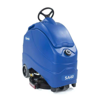
EasyManua.ls Logo

Clarke SA40 56104487 (20D) User Manual

Clarke SA40 56104487 (20D)
127 pages
To Next Page IconTo Next Page
Page #1 background imageLoading...
Page #1 background image
SA40
03/2016, Form No. 56043173
English
Service Manual
Clarke SA40 Models: 56104487 (20D)

Table of Contents

Questions and Answers:

Clarke SA40 56104487 (20D) Specifications

General IconGeneral
BrandClarke
ModelSA40 56104487 (20D)
CategoryScrubber
LanguageEnglish

Summary

General Information

Machine Configurations

Details the SA40 machine's suitability for various applications and its brush deck.

Service Manual Purpose and Application

Explains the manual's role in aiding service personnel for maintenance and repair.

Revision History

Records revisions made to the manual.

Other Reference Manuals and Information Sources

Lists related manuals and where to find them.

Diagnostic and Service Tools

Lists required tools for troubleshooting and repair.

Conventions

Explains references like front/rear as seen from the operator's position.

Parts and Service

Specifies who should perform repairs and how to obtain parts.

Modifications

Outlines restrictions on customer modifications and warranty implications.

Nameplate

Locates and explains the purpose of the machine's nameplate.

Cautions and Warning Symbols

Explains the meaning of danger, warning, and caution symbols used.

General Safety Instructions

Provides essential safety precautions for operating the machine.

Prop Rod

Describes the use of the prop rod for safety when accessing components.

Moving the Machine

Explains how to manually override the drive brake to move the machine.

Transporting the Machine

Lists precautions to take before transporting the machine.

Specifications

General Specifications

Lists overall technical specifications for the SA40-X20D model.

Overall Dimensions

Provides detailed dimensional drawings and measurements of the machine.

Fastener Torque Specifications

Lists torque values for various fastener sizes in different materials.

Maintenance

General Maintenance Information

Emphasizes following the maintenance schedule for optimal condition.

Maintenance Schedule

Provides a schedule of daily, weekly, monthly, and yearly maintenance tasks.

Lubrication Locations

Identifies components requiring monthly lubrication with grease or oil.

Machine Controls

Key Switch, Emergency Stop and Horn Switch

Describes the function of essential control panel switches.

Circuit Breakers

Details the function and location of the machine's circuit breakers.

Speed and Direction Controls and Indicators

Explains controls for speed adjustment, direction selection, and indicators.

Scrub Controls and Indicators

Describes switches and indicators for scrub pressure and operation.

Solution Controls and Indicators

Explains controls for solution flow rate and indicators.

Vacuum Power Adjustment Switch and Indicators

Details controls for vacuum power levels and indicators.

Information Switch

Describes the information switch and the data it displays on the screen.

Battery Status Screens

Explains the battery status display and low voltage cut-off conditions.

Chassis System

Major Chassis Components

Identifies and illustrates the main structural components of the chassis.

Platform Switches

Explains the operator presence and go pedal switches on the platform.

Control System

Functional Description

Describes the main controller (A1) and speed controller (Curtis 1210).

Component Locations

Shows the physical location of the A1 Control Board and speed controller.

Fault Codes

Explains how fault codes are displayed on the graphic display.

Fault Code Table

Lists fault codes, descriptions, and conditions required to set them.

System Disabled by Fault Codes

Details which systems are disabled and indicators for various fault codes.

Service Test Mode

Explains how to access and use the service test mode for troubleshooting.

Service Test Mode Functions

Details how control panel switches function within the service test mode.

Programming Options

Main Menu Access

Step-by-step guide on how to access the programming options menu.

Deck Type

Function to specify the type of deck installed in the machine.

Low Battery Voltage Cutout

Configures the voltage level for automatic shutdown to protect batteries.

Battery Charger

Discusses battery charger selection and compatibility.

Burst Of Power Operation

Notes that this feature is not supported on the SA40.

Detergent (EcoFlex™) Option

States that this option is not applicable to the SA40.

Chemical Rate Bias

States that this option is not applicable to the SA40.

Open Fault Detect

Allows disabling open circuit faults for troubleshooting.

Display Rev Level

Shows the software revision level of the A1 Control Board.

Lock Out Brush Pressure

Allows locking out specific scrub pressure settings for operators.

Lock Out Solution Flow Rate

Allows locking out specific solution flow rate settings.

Backup Alarm Volume

Adjusts the volume for backup alarms.

Forward Alarm Volume

Adjusts the volume for forward movement alarms.

Horn Volume

Adjusts the volume for the horn.

Restore Defaults

Resets programmed options to factory default values.

Fault Recall

Allows recalling logged error codes for troubleshooting.

Service Test Mode

Cross-references to the Service Test Mode section.

Extra Information on the Graphic Display

Configures additional real-time data display on the graphic screen.

Frozen Parameters

Allows viewing machine parameters saved before an error was detected.

Panel Test

Verifies function of control panel switches and LEDs.

Save Scrub Settings

Determines if scrub settings are saved or defaults are used.

Removal and Installation

A1 Control Board

Step-by-step instructions for removing and installing the A1 Control Board.

E1 Curtis 1210 Speed Controller

Step-by-step instructions for removing and installing the speed controller.

A1 Control Board Shop Measurements

Electrical System

Functional Description

Provides an overview of the machine's electrical system components and power.

On-board Battery Charger

Describes the optional on-board battery charger.

Interlock Circuit

Explains how the interlock circuit prevents propulsion during charging.

Delta-Q Charging Profiles and Charging Progress

Explains how to select charging profiles for different battery types.

Delta-Q Battery Charging Profile Table

Lists battery manufacturers, models, and compatible charging profiles.

Component Locations

Shows the location of electrical components like batteries and charger.

Wiring Diagrams

Wiring (Ladder) Diagram

Presents the ladder diagram for the machine's electrical system.

Wiring Harness Diagram

Shows the wiring harness layout for component connections.

Electrical Connector Pin-out Assignments

To Locate and Identify a Connector

Guides users on how to find and identify specific connectors.

J1 (Molex Mini Fit Jr. 39012105)

Details pin-out assignments for connector J1.

J2 (Molex Mini Fit Jr. 39012125)

Details pin-out assignments for connector J2.

J3 (Molex Mini Fit Jr. 39012145)

Details pin-out assignments for connector J3.

J4 (39012185)

Details pin-out assignments for connector J4.

X2 (Ducon 12147067)

Details pin-out assignments for connector X2.

X6 (Delphi 12052613)

Details pin-out assignments for connector X6.

X7 (Delphi 12015792)

Details pin-out assignments for connector X7.

X126 (AMP 282087-1)

Details pin-out assignments for connector X126.

X127 (Delphi 15363990)

Details pin-out assignments for connector X127.

X139 (Delphi 12020786)

Details pin-out assignments for connector X139.

X143 (Ducon 12147067)

Details pin-out assignments for connector X143.

X144 (Delphi 12015792)

Details pin-out assignments for connector X144.

X161 (Delphi 12020926)

Details pin-out assignments for connector X161.

Recovery System

Functional Description

Explains how the recovery system pulls wastewater using a vacuum motor.

Circuit Descriptions

Describes the circuit logic for the vacuum motor.

Vacuum Motor Off

Describes the circuit conditions when the vacuum motor is off.

Vacuum Motor On

Describes conditions and voltage measurements for the vacuum motor when on.

Component Locations

Shows the physical location of recovery system components like the tank and motor.

Bench-testing the Flyback Diode (bridge rectifier)

Provides steps for testing the flyback diode using a multimeter.

Removal and Installation

Vacuum Motor

Step-by-step instructions for removing and installing the vacuum motor.

Scrub System

Functional Description

Explains the scrub system, its components, and deck positions.

Scrub Deck and Motor

Details the 20D scrub deck, brush motor, and related assemblies.

Brush Motor Contactor (K2)

Describes the function of the brush motor contactor (K2).

Deck Actuator Assembly

Explains the deck actuator assembly and its four positions.

Circuit Descriptions

Describes the circuit logic for the scrub brush motor.

Scrub Brush Motor Off

Describes the circuit conditions when the scrub brush motor is off.

Scrub Brush Motor On

Describes conditions and voltage for the scrub brush motor when on.

Scrub Deck Up

Explains how the deck actuator raises the scrub deck until the upper limit switch opens.

Scrub Deck in Vacuum-only Position

Describes deck lowering to vacuum-only position and control logic.

Scrub Deck at Normal Scrub Pressure

Explains deck lowering to normal scrub pressure and control logic.

Scrub Deck at Extra Scrub Pressure

Explains deck lowering to extra scrub pressure and control logic.

Component Locations

Shows the location of scrub system components.

Troubleshooting

Lists causes and corrections for scrub system problems.

Brush Motor not running

Lists causes and corrections for the brush motor not running.

Scrub Deck Actuator not running

Lists causes and corrections for the scrub deck actuator not running.

Scrub Deck not being lowered to the vacuum-only position

Lists causes and corrections for deck not lowering to vacuum-only position.

Scrub Deck not being lowered to the normal scrub position

Lists causes and corrections for deck not lowering to normal scrub position.

Scrub Deck

Step-by-step instructions for removing the scrub deck.

Scrub Deck Actuator Assembly

Step-by-step instructions for removing the scrub deck actuator assembly.

Scrub Deck Actuator Adjustment

Details how to set the scrub deck actuator position correctly.

Solution System

Functional Description

Explains the gravity-feed solution system and its components.

Solution Tank, Water Filter and Valves

Details the solution tank capacity and filter assembly.

Solution Solenoid Valve

Explains the function of the solenoid valve and its duty cycle.

Circuit Descriptions

Describes the circuit logic for the solution solenoid valve.

Solution Solenoid Valve Off

Describes circuit conditions when the solution solenoid valve is closed.

Solution Solenoid Valve On

Describes conditions and voltage for the solenoid valve when open.

Component Locations

Shows the location of solution system components.

Maintenance

Describes upkeep procedures for the solution system.

Cleaning the Water Filter

Provides steps for cleaning the water filter.

Troubleshooting

Lists causes and corrections for solution system problems.

No solution to the Scrub Deck

Lists causes and corrections for lack of solution flow.

Squeegee System

Functional Description

Explains the squeegee assembly and its components.

Component Locations

Shows the location of squeegee assembly components.

Troubleshooting

Lists causes and corrections for squeegee system problems.

Poor water pick-up

Lists causes and corrections for poor water pickup by the squeegee.

Steering System

Functional Description

Explains how the steering system operates to steer the machine.

Component Locations

Shows the location of steering system components.

Troubleshooting

Lists causes and corrections for steering system problems.

The steering is binding or the machine steers “hard”

Lists causes and corrections for hard steering.

Wheel System - Traction

Functional Description

Explains how the drive wheel assembly propels the machine.

Wheel Drive Motor Circuit Descriptions

Details the circuit logic for the drive wheel motor.

Power to the E1 Curtis 1210 Speed Controller

Details conditions required for power to reach the speed controller.

Speed Control Drive Functions

Explains how the speed controller manages motor speed and brake release.

Speed Control Communication with the A1 Control Board

Details the communication wires between the control boards.

Component Locations

Shows the location of traction system components.

Drive Wheel Assembly

Shows the location of the drive wheel assembly.

E1 Curtis 1210 Speed Controller

Shows the location of the speed controller.

Drive Wheel Brake

Shows the location of the drive wheel brake.

Maintenance and Adjustments

Describes maintenance and adjustment procedures.

Speed Control Programming Options

Lists programmable speed control parameters accessible via programmer.

Troubleshooting

Lists causes and corrections for traction system problems.

General Troubleshooting

Lists causes and corrections for machine not moving.

E1 Curtis Speed Controller Diagnostics

Explains methods for diagnosing controller faults.

Diagnostics Method A - Graphic Display and Direction Indicator

Explains using display and indicators for controller fault codes.

Diagnostics Method B - Curtis Programmer

Explains using the Curtis programmer for diagnostics.

Diagnostic History

Explains accessing and clearing the controller's diagnostic history.

Status LED Fault Code Table

Lists LED fault codes, explanations, and possible causes.

Removal and Installation

Describes procedures for removing and installing components.

Drive Wheel Assembly

Step-by-step instructions for removing the drive wheel assembly.

Drive Wheel Motor

Step-by-step instructions for removing the drive wheel motor.

Steering Spindle Bearings

Step-by-step instructions for removing and replacing bearings.

Drive Wheel Motor Maintenance

Describes maintenance procedures for the drive wheel motor.

Replacing the Motor Brushes

Step-by-step instructions for replacing motor brushes.

Specifications

Shop Measurements

Lists pin measurements for the E1 Curtis 1210 Speed Controller.

E1 Curtis 1210 Speed Controller – Output

Lists output measurements for the speed controller.

General Specifications

Lists general specifications for the drive wheel motor and controller.

Special Tools

Related product manuals