10
© Copyright 2020. All rights reserved.
The recirculation ow is designed to be 1.2-1.8 times
that of the average design inow. Table 4 indicates
starting ow rates for each unit. However, ne
adjustments may be necessary to ensure optimum
performance.
Setting the flow rate:
• Adjust the ow using rates in Table 4.
• The ow rate is adjusted by rotating the gray
recirculation valve (2) and observing the ow at the
pipe end.
• There are prescribed lines at the outlet of the
recirculation pipe to aid in approximating the correct
ow.
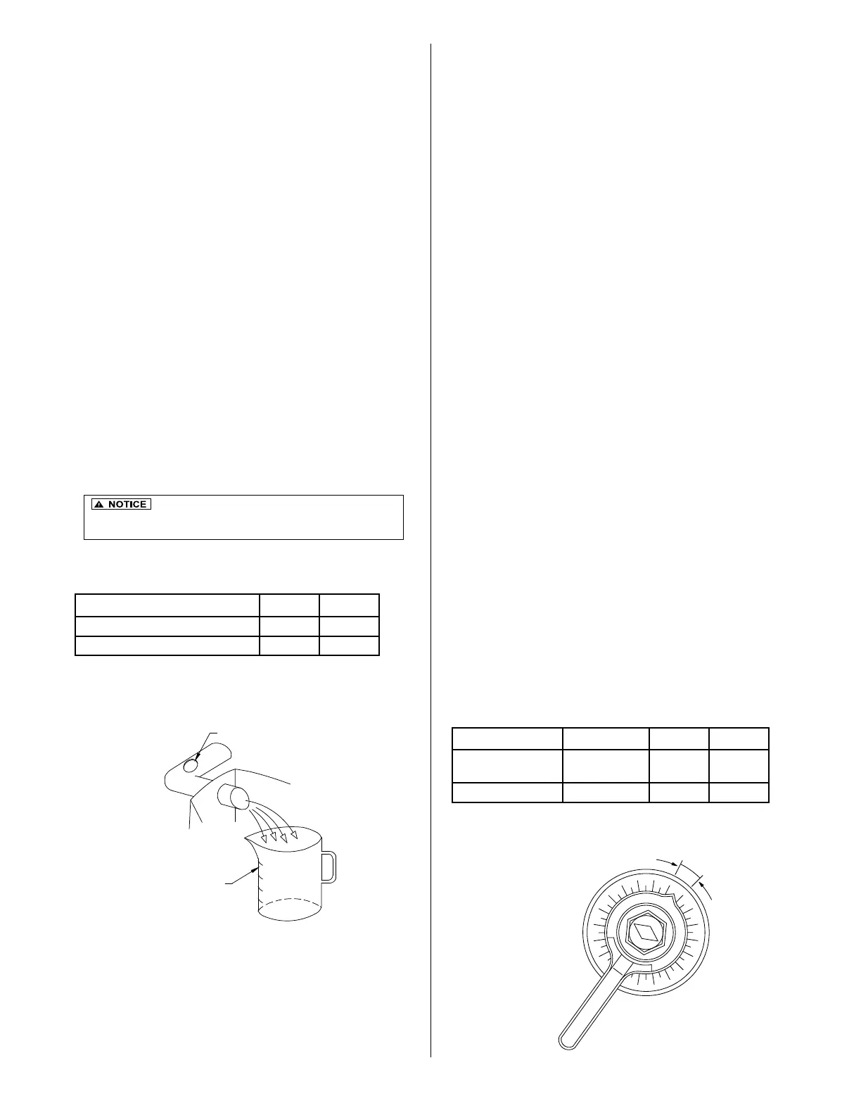
Measuring the flow rate:
• The actual ow rates must be measured to verify
ow after adjustment of the valve and observation
at the pipe end.
• Measure the time in seconds required to ll a 1L
container.
• Compare the time to value ranges in Table 4.
• If necessary, adjust the valve again and collect
another sample to verify the correct ow rates.
In order to prevent plugging of the media in the
aeration chamber, the backwash cycle activates
at a preset schedule. If there is no backwash cycle
or if the backwash cycle is too short, the unit’s
performance will be adversely affected. Likewise, if
the backwash cycle is too long, performance will be
compromised.
The backwash cycle begins at 2:00 AM and lasts for
ve minutes. One hour later, another ve minute
backwash cycle occurs. The backwash initiation
time can be set for any time during a 24-hour period
to accommodate unusual water use patterns. The
goal is to set the time when there is no ow into the
unit.
The backwash cycle and sludge transfer from the
aeration chamber takes place in the same action.
Verify that the air ow is uniform across the
aeration chamber during a backwash cycle. If not,
adjust the red backwash valve (3) accordingly.
Setting the ow rate:
• On all HIBLOW HP series model blowers, press
the [MINUTE] button for at least 2 seconds to
switch to manual mode. The "aeration" and
"backwash" can be switched by the [MINUTE]
button.
• Set the backwash ow rate by adjusting the
gray sludge transfer valve (4). Use Table 5 to
determine the setting for each Fusion
®
model.
Measuring the ow rate:
• Measure the actual backwash ow rate at the
outlet of the sludge return pipe in the rst
chamber the same way the recirculation ow rate
is measured.
• Adjust the gray sludge transfer valve (4) if
necessary to obtain the proper ow.
• Be sure to press [SET] to return the unit back to auto
mode on HIBLOW Unit.
It is important not to set the ow rate too high
because it can cause excessive agitation within the rst chamber
(Sedimentation Chamber). This could result in poor performance.
RECIRCULATION FLOW ADJUSTMENT
BACKWASH FLOW ADJUSTMENT
Table 5 - Backwash Flow Rate Setting
Model Frequency ZF450 ZF800
Backwash ow
rate (sec/liter)
Twice/day 7-10 4-6
Valve open (%) Twice/day 50-55% 40-45%
Figure 15 - Flow
Controlling Valve
Figure 14 - Flow
Measurement
Model ZF450 ZF800
Recirculating ow rate (sec/liter) 29-45 14-22
Suggested Valve Opening 35-40% 30-35%
Table 4 - Recirculation Flow Rates
20
30
40
50
60
70
80
90
100
0
10
MCL
SUGGESTED
RANGE
RECIRCULATION OR BACKWASH PIPE
CONTAINER
G.L
WATER
TO TREATMENT UNIT
FAUCET
BACKFLOW PREVENTER
HOSE
BLOWER
CLAMP
EXISTING AIR LINE
BRUSH
20
30
40
50
60
70
80
90
100
0
10
MCL
SUGGESTED
RANGE
RECIRCULATION OR BACKWASH PIPE
CONTAINER
G.L
WATER
TO TREATMENT UNIT
FAUCET
BACKFLOW PREVENTER
HOSE
BLOWER
CLAMP
EXISTING AIR LINE
BRUSH
 Loading...