14
© Copyright 2020. All rights reserved.
AERATION CHAMBER CLEANING
1. Aeration
The aeration system must be ushed every maintenance
visit. There are two ushing methods: (A) Air ushing and (B)
Water ushing. Air ushing must be done every maintenance
visit. Water ushing may be done if there is a sign of
clogging in the aeration chamber (e.g. abnormal increase in
recirculation ow).
(A) Air ushing procedure:
• Make sure the blower is in the aeration mode.
• Make sure a check valve or backow preventer is present
for water ushing procedure.
• Close gray recirculation valve (2) all the way. (0%)
• Rotate blue aeration valve (1) back and forth from the 0%
to the 100% position several times to ush.
• Set valves (1) and (2) back to the appropriate positions.
(See Recirculation Flow Adjustment, pg. 10)
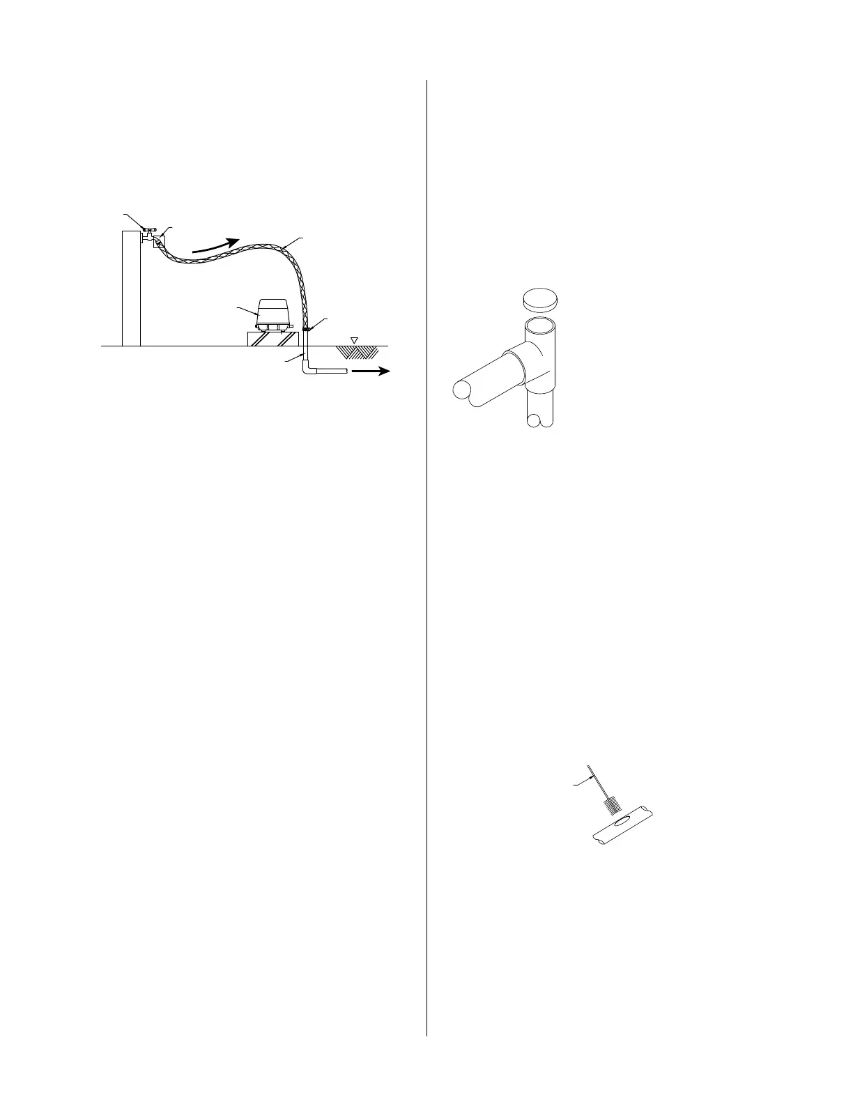
(B) Water ushing procedure: (See Figure 18)
• Make sure the blower is off.
• Close valve (2) all the way.
• Connect a water line to the aeration line as shown in
Figure 18.
• Gradually open the water faucet and introduce water
into the system.
• Rotate valve (1) back and forth from the 0% to the 100%
position several times to ush.
• Turn off the water, remove the water line, and reconnect
the air line to the blower.
• Set valves (1) and (2) back to the appropriate positions.
(See Recirculation Flow Adjustment, pg. 10)
(C) Cleaning the recirculation line:
• Make sure the blower is in the aeration mode. If not,
change the mode by pressing the Manual Backwash
button.
• Open the gray recirculation valve (2) to 100%.
• Flush water through the recirculation line for several
seconds.
• Turn off the recirculation by rotating the gray valve
(2) to 0%.
• Make sure the blower is off. Allow the system to
relax for a few seconds.
• Repeat this cleaning method three times.
• A hose or brush can also be used to clean the recirculation
line. See Figure 20.
• Reset the gray valve (2) to its original position.
2. Backwash
The backwash system must be ushed every maintenance.
There are two ushing methods: (A) Air ushing and
(B) Water ushing. Air ushing must be done every
maintenance visit. Water ushing must be done if there is
a sign of clogging in the aeration chamber (e.g. abnormal
increase in recirculation ow).
(A) Air ushing procedure:
• Make sure the blower is in the backwash mode.
• Close the gray sludge transfer valve (4) all the way.
• Rotate the red backwash valve (3) back and forth from the
0% to the 100% position several times to ush.
• Set valves (3) and (4) back to the appropriate positions.
(See Backwash System)
20
30
40
50
60
70
80
90
100
0
10
MCL
SUGGESTED
RANGE
RECIRCULATION OR BACKWASH PIPE
CONTAINER
G.L
WATER
TO TREATMENT UNIT
FAUCET
BACKFLOW PREVENTER
HOSE
BLOWER
CLAMP
EXISTING AIR LINE
Figure 18
(B) Water ushing procedure:
(See Fig. 19)
• Make sure the blower is off.
• Close valve (4) all the way.
• Connect a water line to the backwash
airline as shown in Figure 18.
• Gradually open the water faucet and
introduce water into the system.
• Rotate valve (3) back and forth from
the 0% to the 100% position several
times to ush.
• Turn off the water, remove the water line, and reconnect the
airline to the blower.
• Set valves (3) and (4) back to the appropriate positions. (See
Backwash System)
(C) Cleaning the sludge transfer line:
• Make sure that the blower is in the backwash mode. If
not change the mode by pressing Manual Backwash.
• Open the gray sludge transfer valve (4) to 100%.
• Flush water through the sludge transfer line for a few
seconds.
• Repeat this cleaning method three times.
• A hose or brush can also be used to clean the sludge
transfer line. See Figure 20.
• Reset the gray valve (4) to its original position.
• Return the blower to the normal aeration mode. by
pressing Manual Backwash.
3. Foam formation
Make sure there is not an excess amount of foam on the
surface. If excessive foam is present it may indicate high
detergent usage. Meet with owners to inform and educate
them concerning excessive use.
4. Abnormal water level
If the water level exceeds the partition wall, clean the plastic
cage rst with a brush, then check for possible clogging in the
lter media section. Clogs may be cleared by using a manual
backwash tool. The manual backwash tool may also be used
to eliminate a clog in the anaerobic chamber media as well.
Figure 19
20
30
40
50
60
70
80
90
100
0
10
MCL
SUGGESTED
RANGE
RECIRCULATION OR BACKWASH PIPE
CONTAINER
G.L
WATER
TO TREATMENT UNIT
FAUCET
BACKFLOW PREVENTER
HOSE
BLOWER
CLAMP
EXISTING AIR LINE
BRUSH
Figure 20
 Loading...