6
1
DIMMER / STOPPER / STROBE
2
PAN
3
TILT
CHANNEL FUNCTIONS AND OPTIONS
3
The wires must not come into contact with each other or with the metal
casing of the plug.
The casing of the plug/socket must be connected to the screen and to pin 1
of the connectors.
Having completed the operations described above, press the on/off switch (9).
Check that the lamp comes on and the auto-reset sequence starts.
•
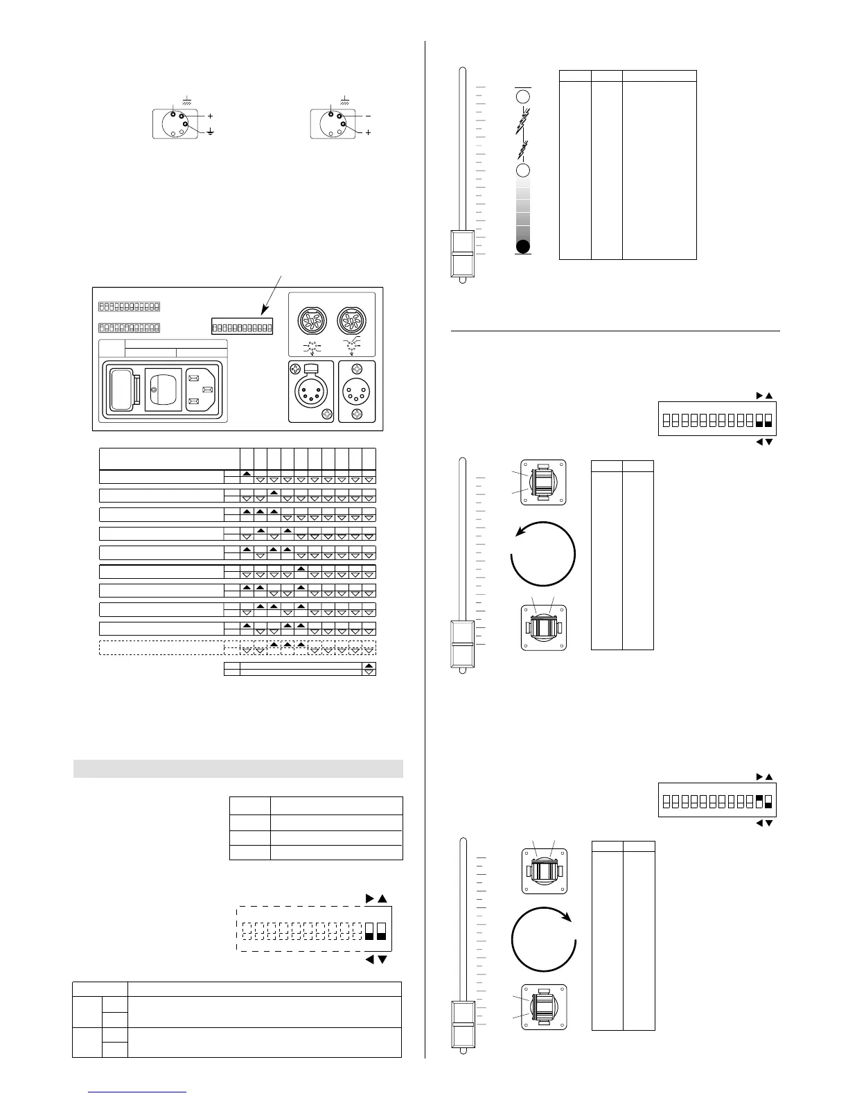
Projector address codes (for digital signals)
A single PIN SCAN projector utilizes 3 control channels.To ensure that the different
projectors are addressed correctly by the controller, a code must be assigned to
each one.The operation is carried out on each PIN SCAN by setting the microswitch-
es as indicated in the table below.
Setting the TEST switch to the ON position for a few seconds with the projector
powered-up, an auto-reset routine is carried out. Leaving the TEST switch at the
ON position for a longer period, a full self-test program will be completed; once the
operation has terminated, return the switch to the OFF position.
CHANNEL
FUNCTION
ON
Pan direction change.
OFF
ON
Tilt direction change
OFF
11
12
OPTION FUNCTION