7
CAUTION:
- When fitting a new lamp read the manufacturer's instructions carefully.
- The lamp must always be changed without delay if damaged or deformed by heat.
• Changing fuses
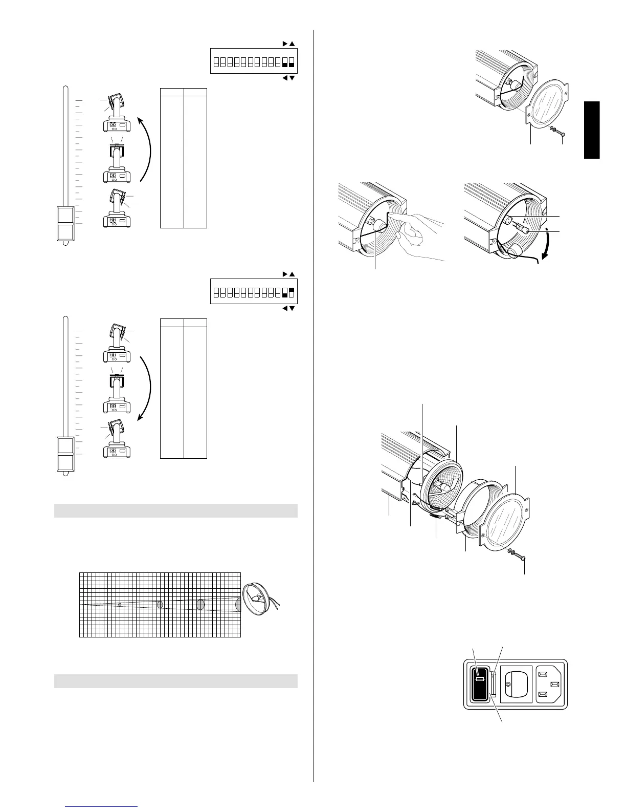
To change the fuses, press the tab (18) and
pull out the fuse holder (19). Replace any
blown fuse with one of the same type and
rating as indicated on the label (20)
attached to the holder (19). Insert the fuse
holder and push in to engage the tab (18).
• Routine cleaning
To maintain the light output of the projector undiminished, parts that tend to accu-
mulate dust and grease must be cleaned periodically.
To remove dirt from the reflector and filter use a soft cloth moistened with any liquid
detergent suitable for cleaning glass.
CAUTION: Do not use solvents or alcohol
IMPORTANT: isolate the projector from the electrical power supply before
commencing maintenance work of any description.
The maximum temperature on the outer surface of the projector under normal
operating conditions is 100°C (212° F).
After switching off, do not remove any part of the projector for at least 10 minutes;
once this time has elapsed, the risk of a lamp exploding is practically zero.If the lamp
needs changing, wait a further 15 minutes to avoid the risk of burns.
In the event of a lamp exploding, the fixture is designed to prevent fragments of glass
from being scattered. The protective filter (2) must be fitted at all times, and if visibly
damaged must be replaced promptly with a genuine spare.
MAINTENANCE
5
2
10
12
11
3
•
Changing the lamp: type HALOSTAR 12V
max 100W with G 6.35 fitting
Use a Phillips screwdriver to unscrew screws
(3) and remove the surround with protective
filter (2); disengage the refraction shield clip
(10) by pushing it slightly towards the interior,
and then turn it towards the outside of the
reflector; now remove the burnt out lamp (11)
from the fitting (12) by pulling it out in a longi-
tudinal direction. Remove the new lamp from
its box and insert it in the fitting (12) ensuring
that the pins are positioned correctly. Refit the
refraction shield clip (10) in its location by
pressing it gently, and then secure the sur-
round with the protective filter by means of
the screws.
• Changing the lamp: type HALOSPOT 12V max 100W with G53 fitting
Use a Phillips screwdriver to unscrew the screws (3), remove the surround with pro-
tective filter (2) and detach front cover (13) from body (14). Disconnect the power
wires (15) from terminals (16) and then detach clips (17) from their supports and
remove the burnt out lamp (12).
Remove the new lamp from its box and place it on the front cover (13); now re-fit the
clips (17) and reconnect the power wires to terminals (16). Remount the front cover
(13) to the body (14), ensuring you do not inadvertently trap the wires between struc-
tural parts of the spotlight; position the surround with protective filter and secure by
means of the screws.
14
15
3
2
13
17
16
12
18
19
20
ENGLISH
 Loading...