EasyManua.ls Logo

CLEAN BURN CB-1400 User Manual

CLEAN BURN CB-1400
108 pages
To Next Page IconTo Next Page
Page #1 background imageLoading...
Page #1 background image
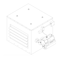
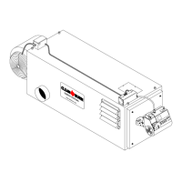
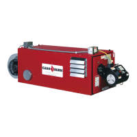
CLEAN BURN MODEL: CB-1400
MULTI-OIL FURNACE
with CB-525-S2 BURNER
IMPORTANT FOR U.S. INSTALLATIONS: All installations must be made in accordance with state and local codes
which may differ from the information provided in this manual. Save these instructions for reference.
IMPORTANT FOR CANADIAN INSTALLATIONS: These instructions have been reviewed and accepted by
Underwriters' Laboratories of Canada as being appropriate for the installation of the ULC labelled products
identified herein. The use of these instructions for the installation of products NOT bearing the ULC label and
NOT identified herein may result in an unacceptable or hazardous installation.
IMPORTANT FOR CANADIAN INSTALLATIONS: The installation of this equipment is to be accomplished by
qualified personnel and in accordance with the regulation of authorities having jurisdiction and CSA Standard B 139,
Installation Code for Oil Burning Equipment.
PUBLICATION DATE: 8/15/07, Rev. 3 CLEAN BURN PART # 43204
U.L. Listed Used Oil
Burning Appliance
#MH15393 (N)
U.L.-C Listed
#CMP217
WARNING: DO NOT assemble, install, operate, or maintain this equipment without first
reading and understanding the information provided in this manual. Installation and
service must be accomplished by qualified personnel. Failure to follow all safety precautions
and procedures as stated in this manual may result in property damage, serious personal injury
or death.
I88817
OPERATOR'S MANUAL

Table of Contents

Questions and Answers:

CLEAN BURN CB-1400 Specifications

General IconGeneral
ModelCB-1400
TypeFurnace
BTU/HR INPUT140, 000
Fuel TypeOil
Fuel Consumption (GAL/HR)1.0
Electrical115V, 60Hz, 1Ph
Tank Capacity275 Gallons

Summary

WARRANTY INFORMATION

LIMITATIONS

Details the restrictions and conditions that apply to the manufacturer's warranty agreement, including exclusions and obligations.

TRADEMARKS

COPYRIGHT

SECTION 1: INTRODUCTION

Guide to this Manual

Provides an overview of the manual's contents and structure for safe installation and operation.

For Your Safety

Details safety statements, warnings, and precautions for operating the furnace, covering statement types and general safety rules.

Guidelines for Furnace Usage

Outlines proper usage, approved fuel types, and EPA regulations for the furnace operation.

Guidelines for Used Oil Tanks

Provides safety guidelines for the installation and storage of used oil supply tanks according to national and local codes.

Safety Labels

Identifies the location and description of all safety labels on the furnace cabinet for user awareness.

SECTION 2: UNPACKING

Removing the Shipping Crate

Instructions for safely removing the furnace from its shipping crate and pallet, emphasizing proper handling.

Unpacking and Inspecting All Components

Guide to unpacking and checking all furnace components for damage or shortages, noting notification procedures.

Warranty Registration

Instructions for completing and returning the warranty registration card for proper coverage within 30 days.

SECTION 3: FURNACE ASSEMBLY

Understanding Assembly

Overview of the furnace assembly steps, including observation port, fan assembly, and burner installation.

Required Tools and Materials

Lists the necessary tools and materials required for furnace assembly procedures.

Installing the Observation Port

Step-by-step guide on correctly installing the observation port for safe flame viewing.

Installing the Fan Assembly

Instructions for installing the fan assembly, including motor cable connection and wiring.

Installing the Burner

Procedures for checking the burner nozzle/electrodes and mounting the burner assembly.

Mounting the Burner on the Hinge Bracket

Detailed steps for mounting the burner onto the hinge bracket and securing it in the firing position.

Installing the Connector Block, Oil Line Tubing, and Air Line Tubing

Guide for installing the connector block, oil line, and air line tubing to the burner and furnace.

Locking the Burner into Firing Position

Final steps to secure the burner in its firing position and connect the electrical cable.

SECTION 4: FURNACE INSTALLATION

Understanding Installation

Outlines the multi-step process for furnace installation and reviews necessary safety statements and codes.

Selecting a Location

Guidelines for choosing a suitable location for the furnace, considering clearances, access, and combustion air.

Mounting the Furnace

Details on constructing mounting systems for ceiling, raised platform, or floor installation, ensuring stability.

Oil Tank Installation Specifications

Requirements and safety guidelines for installing the used oil supply tank, including size, venting, and maintenance.

Installing the Metering Pump

Procedures for preparing and mounting the metering pump, including vertical and horizontal positions and optimal placement.

Wiring the Furnace and Pump

Instructions for connecting the dedicated electrical circuit to the furnace and the pump, ensuring proper power supply.

Installing the Suction Oil Line Components

Critical specifications for airtight suction oil line installation from tank to pump, ensuring proper flow and preventing leaks.

Installing the Stack

Recommendations for stack design, specifications, and installation order for proper draft and exhaust.

Installing the Wall Thermostat

Steps for selecting a location, mounting, and wiring the wall thermostat for furnace control.

SECTION 5: METERING PUMP PRIMING

Understanding Metering Pump Priming

Explains the importance of sequential, uninterrupted priming for the metering pump to ensure correct operation.

Required Tools and Materials

Lists the tools and materials needed for oil pump priming procedures, ensuring all items are gathered beforehand.

Preparing the Burner for Use with the Metering Pump

Instructions for removing the oil regulator to prepare the burner for the metering pump system.

Priming the Metering Pump

Detailed steps for bleeding air and filling the pump and oil lines with oil to ensure a solid oil stream.

Vacuum Testing the Oil Pump

Procedure to test the pump and fittings for airtightness and proper vacuum pull, critical for suction leaks.

SECTION 6: STARTING AND ADJUSTING THE BURNER

Understanding Burner Startup and Adjustment

Overview of the sequential procedures for burner startup and adjustment, emphasizing safety and correct operation.

Preparing the Burner for Startup

Steps to prepare the burner, including setting the air regulator and combustion air band for initial ignition.

Starting the Burner

Instructions for starting the burner, adjusting air regulator, and observing flame length for optimal combustion.

Checking the Operation of the Fan Motor

Procedure to verify the fan motor operation and its cycling with the fan limit control for proper heat exchange.

SECTION 7: RESETTING THE OIL PRIMARY CONTROL

Understanding the Oil Primary Control

Explains the safety lockout and recycle mode of the oil primary control, crucial for burner safety.

Using the Reset Button

Steps for safely resetting the oil primary control after a shutdown, with critical warnings about oil mist and heat.

SECTION 8: ADJUSTING THE DRAFT OVERFIRE

Understanding the Importance of Draft

Explains how draft is created and its essential role in furnace combustion and safe exhaust of gases.

Checking for Correct Draft Overfire

Procedure for using a draft gauge to measure and verify correct draft overfire, essential for furnace performance.

Adjusting the Barometric Damper

Instructions for adjusting the barometric damper to achieve the proper draft overfire range for optimal burner operation.

Solving Draft Overfire Problems

Identifies causes of backdraft and suggests solutions like stack design and air adjustments.

Understanding the Effect of Exhaust Fans on Draft

Explains how exhaust fans can cause negative pressure and backdraft issues by removing building air.

Checking Draft Overfire to Determine Severity of Backdraft

Procedure to test the impact of exhaust fans on draft by observing changes in overfire readings.

Installing a Make-up Air Louver

Guidance on sizing and installing make-up air louvers to compensate for exhaust fan air removal and prevent backdraft.

SECTION 9: MAINTENANCE

Understanding Maintenance

Emphasizes the importance of regular maintenance for furnace performance, longevity, and warranty validity.

Periodic Burner Inspection

Guidelines for visually inspecting burner operation, flame, air pressure, and draft for efficient and safe performance.

Filter and Pump Maintenance

Step-by-step instructions for cleaning the canister filter and servicing the metering pump for optimal oil flow.

Tank and Check Valve Maintenance

Guidance on draining the oil tank and cleaning the check valve/screen to ensure proper oil supply.

Furnace Ash Cleaning

Procedures for cleaning ash from the combustion chamber, flues, and stack components to maintain heat transfer.

Annual Burner Tune-up

Recommends annual tune-ups performed by qualified technicians for peak burner condition and performance.

SECTION 10: TROUBLESHOOTING

Flow Chart

Outlines the sequence of furnace operation events to help diagnose problems by tracking the operational flow.

Troubleshooting Tables

Provides tables listing problems, possible causes, and corrective actions for common furnace issues.

APPENDIX A: DETAILED FURNACE SPECIFICATIONS

Furnace Technical Specifications

Lists key technical data for the furnace, including BTUH input, dimensions, and electrical requirements.

Burner Technical Specifications

Provides technical data for the CB-525-S2 burner, such as nozzle size, motor specs, and pressure requirements.

Furnace Dimensions

Illustrates the physical dimensions of the furnace from multiple views, including overall cabinet and fan/burner installed size.

Burner Components (CB-525-S2)

Details the components of the CB-525-S2 burner with part numbers and descriptions for identification.

APPENDIX B: WIRING DIAGRAMS

Furnace Wiring Diagram

Illustrates the electrical wiring connections for the furnace components, including motors and switches.

Burner Wiring Diagram

Shows the electrical wiring connections for the burner assembly and its controls, aiding in troubleshooting.

Ladder Schematic

Provides a ladder schematic of the furnace and burner electrical system for understanding circuit logic.

Metering Pump Wiring Schematic

Details the electrical wiring connections specifically for the metering pump, ensuring correct power supply.

APPENDIX C: FURNACE SERVICE RECORD

Furnace Service Record

A log for recording furnace purchase, installation, inspection, draft readings, and service history for maintenance tracking.

Related product manuals