W
woodarielAug 29, 2025
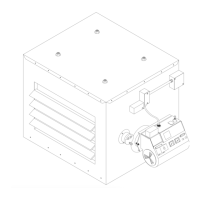
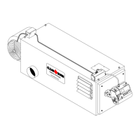
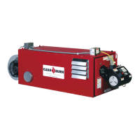
Why does my CLEAN BURN CB-500 Furnace burner shut off on reset periodically?
- BBrian VargasAug 29, 2025
If your CLEAN BURN Furnace burner ignites and runs, but shuts off on reset periodically, such as overnight, consider these potential causes: * Air may be entering the suction oil line due to leaks at the fittings. Perform a vacuum test on the pump as described in Section 5. Re-install and properly seal the suction line fittings to prevent air leaks. * Air may be trapped in a high point in the pressure oil line. Follow the instructions in Section 4 to bleed the air out of the pressure oil line.