FOR-22 4-WIRE INTERFACE
2-6
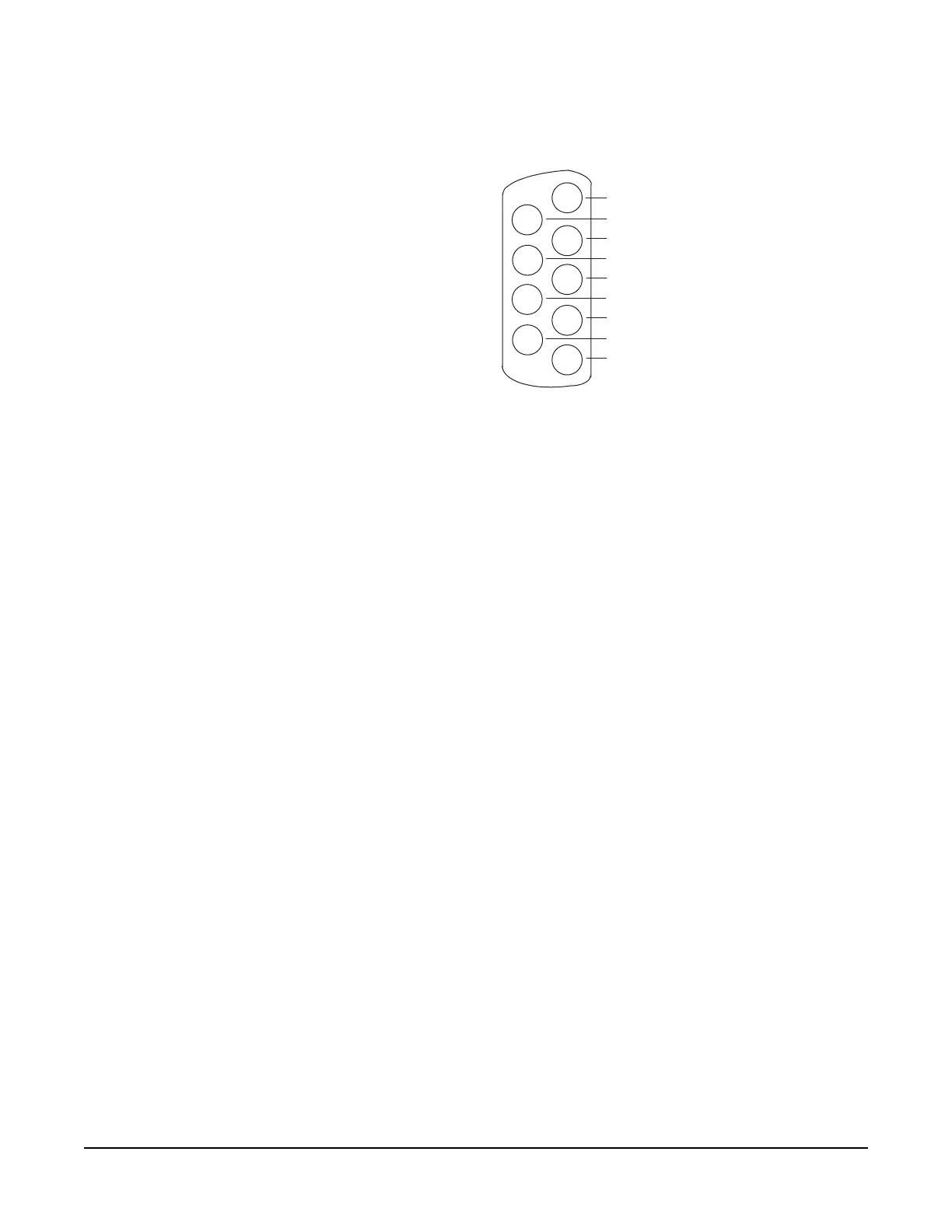
Figure 4: Pinout of the DB-9M I/O Connectors for FOR-22s
EXTERNAL AUDIO DEVICES
Connect external audio devices to the FOR-22 ports through the two DB-9M
connectors labeled "I/O" on the rear panel assembly panel. Both audio input
and output are transformer isolated. Refer to Fig. 4 for pinouts.
CALL SIGNAL INPUT
The Call Signal input is used to receive a "call signal" or logic input from an
external device and send it to the matrix. The voltage across the pins required to
receive a call signal ranges from 4 Volts to 50 volts; it can be either positive or
negative polarity or AC. The input will draw between 4 and 8 milliamps. Refer
to Figure 4 for pinouts.
RELAY CONTACTS
Each FOR-22 channel features a relay that is associated with the logical "call
signal" output of a port. A relay's function depends on the function assigned to
the FOR-22 port in the configuration software. A relay can be assigned to
operate with any label in the system: when that label is activated (either by a talk,
listen, or both as set from the configuration program), the relay will be activated.
Or it can be assigned to be activated by a call signal, for example to operate a
2-way radio transmitter.
You can use the relay to activate an external device, such as an applause light in a
studio, a cue light, or a security door lock. The relays feature both "normally
open" and "normally closed" contacts. The contacts are rated at 1 Amp at 24
volts DC; they are not designed for switching mains AC line voltage. Refer to
Figure 4 for pinouts.
Audio Input
Logic Input (+/- 4 to 50 V)
Relay Normally Open
Audio Output
Audio Output
Audio Input
Relay Normally Closed
Relay Wiper
FOR-22 I/O DB-9M
Logic Input (+/- 4 to 50 V)
1
2
9
8
7
6
5
4
3