FOR-22 4-WIRE INTERFACE
2-5
WIRING
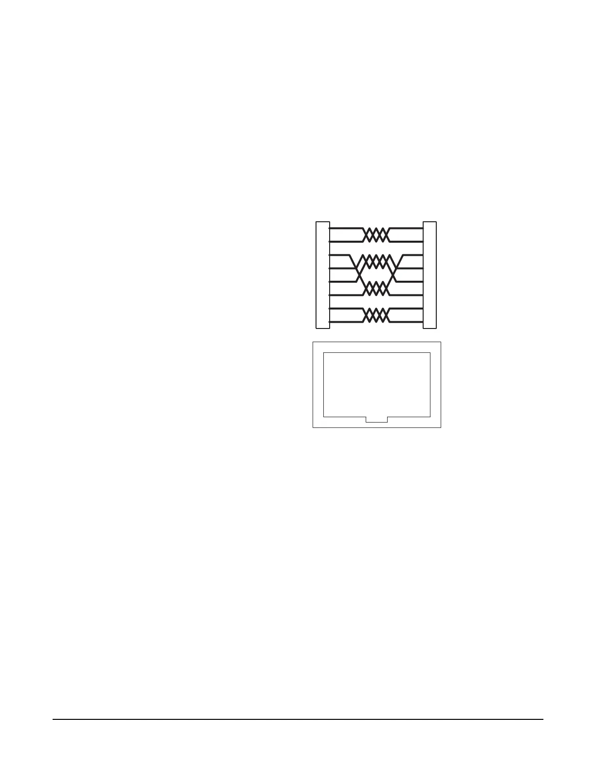
The FOR-22 interface connects to an Eclipse matrix through the two RJ-45
connectors on the IMF-3 or IMF-102 rear-panel assembly to which the FOR-22
unit is connected. One RJ-45 connector is for the first channel of the interface.
The second RJ-45 connector is for the second channel. Figure 3 shows pin
assignments of the RJ-45 connectors used to connect the interface to an Eclipse
matrix.
Figure 3: Matrix to Interface Frame Wiring
The "user" side of the FOR-22 for each channel is on a DB-9M connector on the
rear of the IMF-3 or IMF-102 frame. Figure 4 shows the pinout of either one of
these connectors. Each channel is identical.
The following sections describe how to wire for the various type of inputs and
outputs available on this connector:
• External Audio Devices
• Call Signal Input
• Relay Contacts
1
2
3
4
5
6
7
8
Matrix Frame End
Call Receive +
Call Receive -
Audio Receive +
Audio Send +
Audio Send -
Audio Receive -
Call Send +
Call Send -
Call Send +
Call Send -
Audio Send +
Audio Receive +
Audio Receive -
Audio Send -
Call Receive +
Call Receive -
Interface End
ATT-T568B (Modular Jumpers Wired One to One)
Pair 2
Pair 1
Pair 3
Pair 4
Interface Wiring
1 2 3 4 5 6 7 8
Rear View of
Connector
1
2
3
4
5
6
7
8