Do you have a question about the ClearOne PSR1212 and is the answer not in the manual?
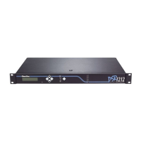
Introduces the PSR1212, its features, and applications.
Details the new functionalities and improvements of the PSR1212.
Lists the items included with the PSR1212 unit.
Describes front and rear panel controls and connectors.
Details the LCD, buttons, and LED indicators on the front panel.
Explains the various connectors and ports on the rear panel.
Explains the expansion bus and network capabilities of the PSR1212.
Outlines power, environment, and software requirements for operation.
Covers power, rack-mounting, and environmental conditions.
Lists the minimum system configuration for G-Ware software.
Illustrates typical hardware connections for the PSR1212 system.
Provides step-by-step instructions for connecting the PSR1212 unit.
Explains how to connect multiple PSR1212 units via the expansion bus.
Details how to physically connect units using the expansion bus.
Explains how to assign unique network addresses to PSR1212 units.
Describes master and slave modes for networked units.
Steps to configure mixer mode via the front panel.
Guides on using the front panel LCD for configuration.
Shows the hierarchical structure of the front panel LCD menus.
Details parameters available in the System menu.
Outlines RS-232 configuration submenus like Baud Rate.
Covers RS-232 flow control and modem configuration.
Lists the minimum system configuration for G-Ware software.
Step-by-step guide for installing the G-Ware software.
Explains how to create and configure site files using G-Ware.
Guides on creating a new site file within G-Ware.
Instructions for adding PSR1212 units to a site file.
Details configuring communication and security properties.
Introduces the Flow and Matrix screens for G-Ware configuration.
Describes the main access window for G-Ware features.
Explains the screen used for routing audio connections.
Details routing audio via expansion bus and processing channels.
Describes routing audio via expansion bus and processing channels.
Details adjusting audio levels at cross points in the matrix.
Covers configuration of inputs 1-8, 9-12, and outputs 1-12.
Configuration details for inputs 1-8, including mute and AGC.
Configuration for line-level inputs 9-12.
Configuration for line-level outputs 1-12.
Details how to label expansion bus inputs and outputs.
Details the eight processing blocks with filters, compressors, and delay.
Covers mute, compressor, filters, and delay configurations.
Adjusting gain and understanding meter readings for processing.
How to assign inputs to gating groups and configure settings.
Explains the concept and benefits of using presets for flexible room configuration.
Guides on how to create presets using G-Ware.
Details options for configuring preset properties like number, name, and protection.
Methods for executing presets using G-Ware or front panel.
Instructions for running presets using G-Ware software.
How to run presets using the PSR1212's front panel.
Explains the function and capabilities of macros.
Explains the two methods for creating macros in G-Ware.
Step-by-step guide for using the Macro Recorder.
Step-by-step guide for creating macros directly in the Macro Editor.
Introduces the utility programs available in G-Ware for system management.
How to use the Signal Generator to create test audio signals.
Utility for comparing configuration information between sites or files.
How to print various configuration reports using G-Ware.
Utility for upgrading the unit's firmware.
Tool for switching between different G-Ware software versions.
Introduces monitoring tools within G-Ware for system status.
How to view gating activity on each mic input.
How to monitor signal levels on inputs, outputs, or processing channels.
Tool for configuring GPIO assignments on Control/Status Port A.
Overview of the Control/Status A port and steps to program its pins.
Tool for configuring XAP IR Remote and ClearOne Control Panels.
Details on using the XAP IR Remote for system control.
Information on connecting and using ClearOne Control Panels.
Covers remote modem access and serial commands via RS-232.
How to access the unit remotely via modem connection.
Information on sending serial commands and creating command strings.
Lists the physical, electrical, and performance specifications of the PSR1212.
Covers RS-232 pinouts and connection diagrams for various devices.
Details pinouts for Control/Status A and B ports.
Pinouts for RS-485, SET, and LINE connectors.
Instructions for installing and connecting control panels.
How to assign a unique ID using DIP switches on control panels.
Explains the wiring process for control panels and daisy-chaining.
Lists available accessories for the PSR1212 with part numbers.
Explains how serial commands are formatted and conventions used.
Lists and describes various serial commands for controlling the PSR1212.
Information about the product warranty and coverage.
Details compliance with FCC Part 15 rules for Class A digital devices.
Safety precautions for equipment installation and connections.
Definitions of technical terms used in the manual.
Alphabetical index of topics and page numbers for quick reference.
| frequency response | 20 Hz to 20 kHz ±1dB |
|---|---|
| noise (EIN) | -126 dBu |
| total harmonic distortion + noise (THD+N) | <0.02% |
| signal to noise ratio (SNR) | 80 dB |
| dynamic range | 100 dB |
| crosstalk | <-91 dB re 20 dBu @ 20 kHz |
| power input range | 100-240 VAC; 50/60 Hz |
|---|---|
| power consumption | 30 W typical |
| +5 VDC pins current protection | 300 mA |
| +15 VDC current protection | 300 mA |
| operating temperature | 32-100° F/0-38° C |
|---|---|
| humidity | 15% to 80%, non-condensing |
| mic/line input impedance | 5 kž |
|---|---|
| mic/line nominal level | adjustable -55 dBu, -25 dBu, 0 dBu |
| mic/line maximum level | -35 dBu, -5 dBu, +20 dBu |
| line inputs impedance | >10 kž |
| line inputs nominal level | 0 dBu |
| line inputs maximum level | 20 dBu |
| outputs impedance | 50 ž |
| outputs nominal level | 0 dBu |
| outputs maximum level | 20 dBu |
| dimensions | 17.25" x 10.25" x 1.25" |
|---|---|
| dimensions metric | 43.8 x 26 x 4.5 cm |
| weight | 7 lb/4.5 kg dry |
| shipping weight | 12 lb/5.9 kg |