Adjustment Procedures Chapter 6
750-177 6-7
Although it is possible to visibly adjust the size of the pilot
flame, it is preferable to obtain a microamp or voltage reading
of the flame signal.
The correct voltage or microamp readings can be found in the
information supplied with the flame safeguard system.
The program relay used may be of the type that provides
message information that includes a constant flame signal of
dc voltage. In this case a separate dc voltmeter is not required.
O. GAS PRESSURE AND FLOW
INFORMATION
Because of variables in both the properties of gas and the
supply system, it will be necessary to regulate the pressure of
the gas to a level that produces a steady, dependable flame
that yields highest combustion efficiency at rated
performance yet prevents overfiring. Once the optimum
pressure has been established, it should be recorded and
periodic checks made to verify that the regulator is holding
the pressure at this level. Occasional modification in fuel
composition or pressure by the supplier may, at times, require
readjustment to return the burner to peak efficiency.
Pressure
The gas supplied must provide not only the quantity of gas
demanded by the unit, but must also be at a pressure high
enough to overcome the pressure-loss due to the frictional
resistance imposed by the burner system and the control
valves.
The pressure required at the entrance to the burner gas train
for rated boiler output is termed “inlet pressure.” The gas
pressure regulator must be adjusted to achieve the pressure to
assure full input.
The inlet pressure requirement varies with boiler size, and
types of gas train. Refer to Table 6-3 for pressure require-
ments.
The pressures listed are based on 1000 Btu/cu-ft natural gas
at elevations up to 700 feet above sea level.
The volume of gas flow is measured in terms of cubic feet and
is determined by a meter reading. The gas flow rate required
for maximum boiler output depends on the heating value
(Btu/cu-ft) of the gas supplied (Table 6-1).
Pressure Correction
The flow rate outlined in Section P is based on a “base”
pressure, which is usually atmospheric or 14.7 psia.
Meters generally measure gas in cubic feet at “line” or supply
pressure. The pressure at which each cubic foot is measured
and the correction factor for the pressure must be known in
order to convert the quantity indicated by the meter into the
quantity which would be measured at “base” pressure.
To express the volume obtained from an actual meter reading
into cubic feet at base pressure, it is necessary to multiply the
meter index reading by the proper pressure factor obtained
from Table 6-2
As An Example:
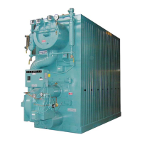
Assume that a 500Flextube boiler is rated for 5MMBtu/hr
input is installed and equipped with a standard gas train; and
that 1,000 Btu natural gas is available with an incoming gas
pressure of 3 psig. The flow requirements can be determined
as follows:
Flow
Since the gas flow rate is based on standard conditions of
flow, correction must be made for the supply pressure through
the meter of 3 psig. Determine the flow rate by dividing the
Btu content of the gas into the burner input (Table 6-1) and
“correct” this answer by applying the correction factor for 3
psig (Table 6-2).
Btu/hr Input = CFH (Cubic feet/hour) Required
Btu/cu-ft
OR
5,000,000 = 5,000 CFH (At 14.7 Ib-atmospheric base
1,000 pressure)
THEN
5,000 = 4237 CFH
1.18
This is the CFH (at line pressure) that must pass through the
meter so that the equivalent full input requirement of 5,000
CFH (at base pressure) will be delivered.
Checking Gas Flow
Your gas supplier can generally furnish a gas meter flow chart
from which gas flow can be determined. After a short
observation period, the information aids in adjusting the
regulator to increase or decrease flow as required to obtain the
rating.
Final adjustment of the gas fuel is carried out by means of
Fine tuning the linkage adjustments, while performing a
combustion efficiency analysis. See Section O for details.
Note: The information given in this section
is for all practical purposes sufficient to set
and adjust controls for gas input. Your gas
supplier can, if necessary, furnish exact
correction factors that take into
consideration Btu content, exact base
pressure, specific gravity, temperature, etc.,
of the gas used.
P. GAS FUEL COMBUSTION

 Loading...


