Page 6
TM12-1105-LG1
08/25/2017
EN
General Safety Instructions Controller
→ Do not modify the nutrunner control, any guard or
accessory unless approved in writing by Apex Tool
Group LLC.
→Donottrytoopenthenutrunnercontrolorthecomponents
of the control. Neither for troubleshooting, nor to perform
other work on the unit. Any interference can cause an
error resulting in serious injury from electrical shock.
Operating with an open controller can cause;
• increased emissions: other equipment may be affected.
• reduced immunity: the nutrunner control may cause
erroneous results.
• Opening the nutrunner control will void existing
warranties.
→ Send the complete nutrunner control for repair to your
Sales & Service Center.
1 Designated use
This product is part of the APEX tightening system and is
intended only for industrial use in fastening processes.
→ Use the nutrunner control only under the following
conditions:
• In conjunction with the APEX tools.
- Corded tools
- Cordless LiveWire EC tools
- Built-in nutrunner
• With the approved APEX accessories and cables.
• With the allowable supply voltage.
• Exclusively at the rate for the nutrunner.
• Usingtheapprovedmaximumcablelength.
• Usingindoorsonly.
• Only in industrial EMC limit value class A
→Donotusethenutrunnercontrol
• in hazardous areas.
• in damp rooms / outdoors.
2 Ambient conditions
→Keepthenutrunnercontrolawayfromheat,re,riskof
explosion and moisture.
3 Required power supply connection
→ Operate only on grounded network (TN network).
Operation in connection with an IT Network is
inadmissible.
4 Install
Danger of crushing. The nutrunner control may fall down
and crush your feet.
→Usesuitableliftingequipment.
→Wearsafetyshoes.
→Ensuresufcientmountingofthenutrunnercontrol:4xM6,
secured against loosening (see Hardare Description
P2174HW).
→Layallconnectedcablesandlinesafely,sothattheyare
not damaged and no one can trip over them.
→Donotexceedatotalcablelengthof65.6ft.(20m).If
longer an APEX isolating transformer, order number
544185PT, is necessary.
In case of failure, high voltage leakage may occur and cause
injuries as mentioned previously.
→ Use enclosed power cable. When changing use a
standard-compliant network management.
→At115VAC:Usecableswithalargercrosssection.
→ Establish equipotential bonding between machine/
workpiece and tool.
→ Before energizing the nutrunner control ensure that all
connections have been properly made (see Hardware
Description P2174W).
5 Before initial operation
→ Before initial operation perform PEmeasure according
to locally applicable regulations (DGUV Vorschrift 3 in
Germany).
→ Observe the safety notes on the nutrunne control and
the tool.
→ Check the nutrunner control, tool, and cable for any
obvious defects.
→ During changeover, cleaning and taking out of service
shut off and disconnect the nutrunner control before
connecting the power and tool cable.
6 Operating
→Immediatelyshutoffthenutrunnercontrolinthecaseof
unusual sound, vibration or odor. Disconnect the power
supplyandhavequaliedpersonnelcheckthetightening
system and repair as necessary.
→Replacedamagedcablesimmediately.
Function Temperature
-13°F to +158°F
(-25°C to +70°C)
Operating
+32°F to +113°F
(0°C to +45°C)
0…90%
non-condensing
up to 9800 ft.
(3000 m)
above sea level
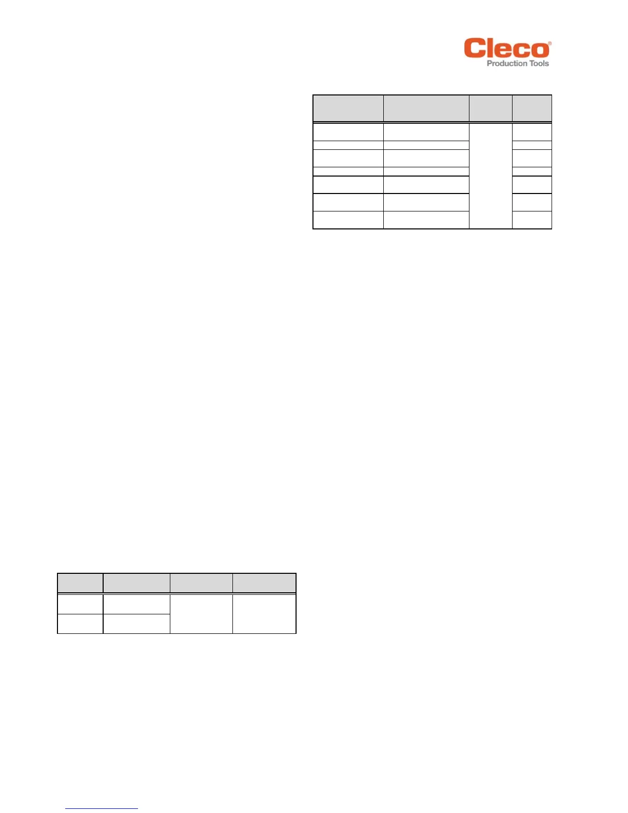
Nutrunner
Control
Input Voltage,
Single Phase
Frequency
Current
mPro400GC-P
115 VAC (104-126 VAC)
230 VAC (207-254 VAC)
mPro400GC-P230 230 VAC (207-254 VAC) 1 A
mPro400GC-S
115 VAC (104-126 VAC)
230 VAC (207-254 VAC)
mPro400GC-S230 230 VAC (207-254 VAC) 1 A
mPro400GC-M
115 VAC - 230 VAC
(104-254 VAC)
1 A - 0.5 A
mPro400GC-E
115 VAC (104-126 VAC)
230 VAC (207-254 VAC)
mPro400GC-I
115 VAC (104-126 VAC)
230 VAC (207-254 VAC)
50-60 Hz
 Loading...