18 PL12EN-1004 2011-01 en02d441_bedingt.fm, 02.02.2011
Pins 2 and 14 must be connected to Pins 1 and 13 respectively.
1.9.4 Connections Utilizing the External 24-volt Supply
(Primary and Master only)
INPUTS: Pins 11 and 23 (Common GND) are the Input “returns”.
• Controller External 24-volt Supply
Pins 11 and 23 will have to return to the GND of the external 24-volt supply.
OUTPUTS: Pins 2 and 14 (Output Common) are the voltage source for the Outputs.
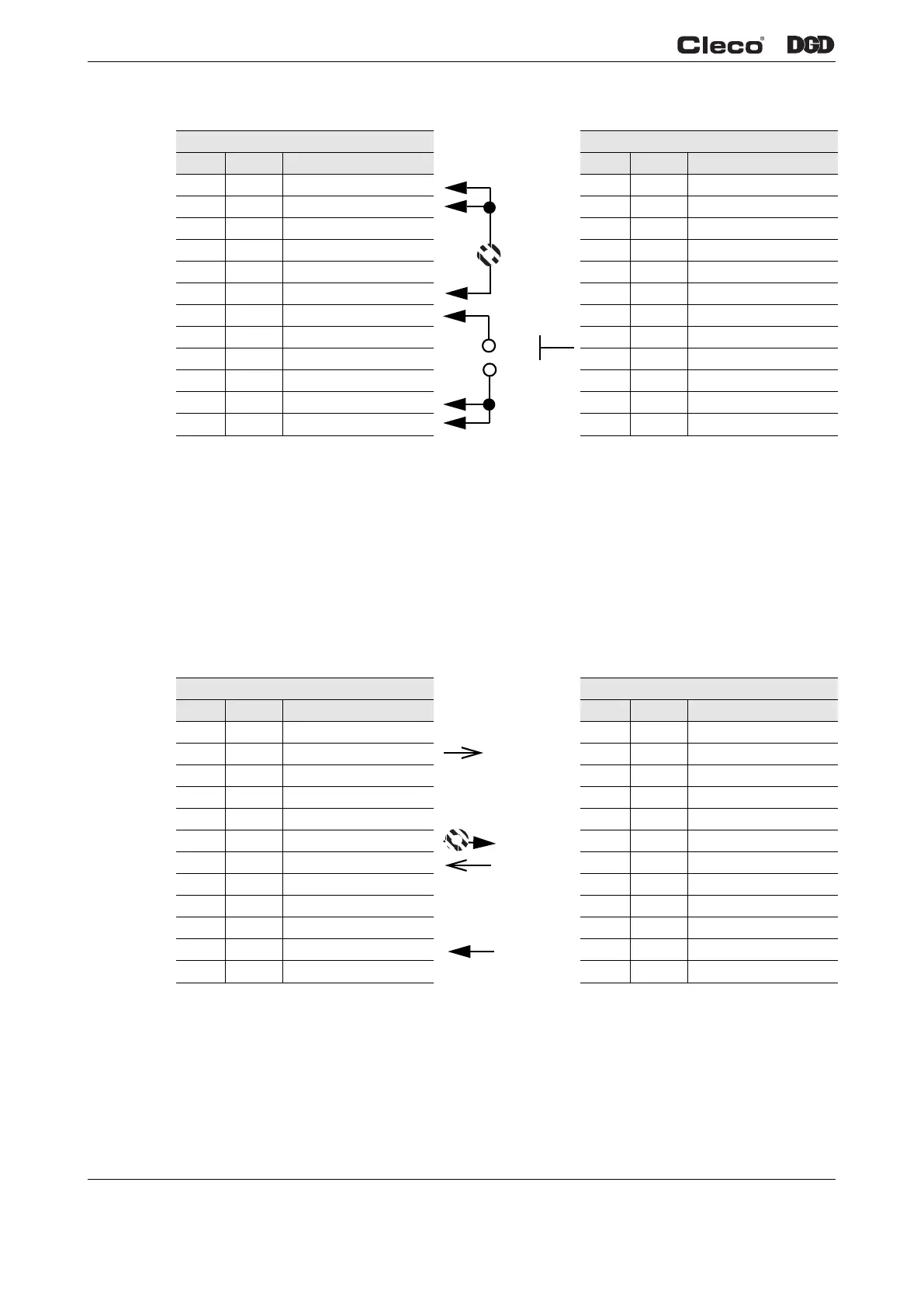
• Controller Internal 24-volt Supply
Pins 2 and 14 must be connected to the external 24-volt supply..
Connector 1 Connector 2
Pin # I/O Description Pin # I/O Description
12 Out GND2 24 Out GND2
11 In Common GND 23 In Common GND
10 Output O 03 22 Output O 07
9 Output O 02 21 Output O 06
8 Output O 01 20 Output O 05
7 Output O 00 (Linking OK) e. g. 19 Output O 04
6 Input I 03 (Tool Start) e. g. 18 Input I 07
5 Input I 02 17 Input I 06
4 Input I 01 16 Input I 05
3 Input I 00 15 Input I 04
2 In Output Common O0-O3 14 In Output Common O4-O7
1 Out +24 V2 13 Out +24 V2
External Ground
External Ground
From External
24 V
From External
24 V

 Loading...