en02d441_bedingt.fm, 02.02.2011 PL12EN-1004 2011-01 17
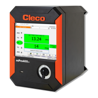
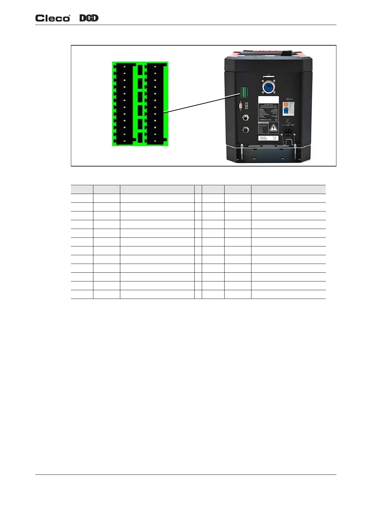
Fig. 1-19 Secondary Pin Configuration
• After address change is a reboot required.
1.9.3 Connections Utilizing the Internal 24-volt Supply
(Primary, Secondary, Master)
INPUTS: Pins 11 and 23 (Common GND) are the Input “returns”.
• Controller Internal 24-volt Supply
Pins 11 and 23 must be jumpered to Pins 12 and 24 respectively.
OUTPUTS: Pins 2 and 14 (Output Common) are the voltage source for the Outputs.
• Controller Internal 24-volt Supply
Pin # I/O Description Pin # I/O Description
12 Out Common GND2 24 Out Common GND
11 In Common GND 23 In Common GND
10 Output O 03 22 Output O 07
9 Output O 02 (Yellow LED) 21 Output O 06
8 Output O 01 (Green LED – OK) 20 Output O 05
7 Output O 00 (Red LED – NOK) 19 Output O 04
6 Input I 03 18 Input I 07
5 Input I 02 17 Input I 06
4 Input I 01 (Reverse) 16 Input I 05
3 Input I 00 (Start) 15 Input I 04
2 N. C. 14 N. C.
1 Out +24 VDC 13 Out +24 VDC
d01223_2.png
Pin 1
Pin 13
Pin 24
Pin 12

 Loading...