16 PL12EN-1004 2011-01 en02d441_bedingt.fm, 02.02.2011
1.9.1 Primary/Master Configuration
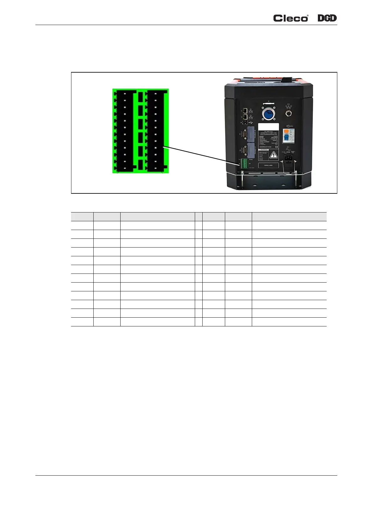
Note: Pins are numbered exactly as they are on the controller, Pins 1 and 13 at the bottom, Pins 12 and 24
at the top.
Fig. 1-18 Primary / Master Pin Configuration
The two I/O connectors are populated with both Inputs and Outputs to help reduce cabling when utilizing
four or less Inputs and Outputs. The I/O can be used with the internal 24-volt supply in the controller or an
external 24-volt supply such as a PLC. The following examples 1.9.3 / 1.9.4 utilize Tool Start as an Input
and Cycle OK as an Output.
1.9.2 Secondary Configuration
Note: Pins are numbered exactly as they are on the controller, Pins 1 and 13 at the bottom, Pins 12 and 24
at the top. Some Inputs and Outputs are fixed, not programmable.
Pin # I/O Description Pin # I/O Description
12 Out GND2 24 Out GND2
11 In Common GND 23 In Common GND
10 Output O 03 22 Output O 07
9 Output O 02 21 Output O 06
8 Output O 01 20 Output O 05
7 Output O 00 19 Output O 04
6 Input I 03 18 Input I 07
5 Input I 02 17 Input I 06
4 Input I 01 16 Input I 05
3 Input I 00 15 Input I 04
2 In Output Common O0-O3 14 In Output Common O4-O7
1 Out +24 V2 13 Out +24 V2
d01223_1.png
Pin 1
Pin 13
Pin 24
Pin 12
 Loading...