INEX SUCTION BLAST CABINET With VACUUM COLLECTOR Page 3
© 2005 CLEMCO INDUSTRIES CORP. • www.clemcoindustries.com • Manual No11217 Rev. E 03/05
2.0 INSTALLATION
2.1 General Installation Notes
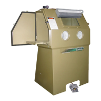
2.1.1 See Figure 1 for the general arrangement. Place
all components in a convenient location where
compressed air and electrical services are available.
The cabinet location must comply with OSHA and local
safety codes. Allow for full access to all doors and
service areas, and for efficient handling of large parts.
Determine the best location, and position all units before
final assembly.
2.2 Connect Compressed Air Supply Line
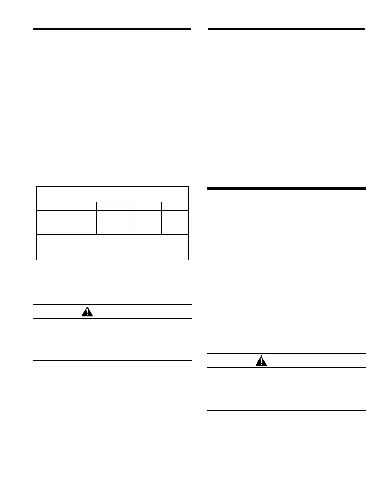
2.2.1 See the table in Figure 3 to determine the
minimum ID of air supply line to the cabinet air inlet. A
smaller diameter hose may reduce blasting efficiency.
Jet Size
Air Line Length No. 4 No. 5 No. 6
25 feet 3/4" 3/4" 1"
50 feet 3/4" 3/4" 1"
75 feet 3/4" 1" 1"
100 feet 3/4" 1" 1"
Minimum compressed air line ID
Figure 3
2.2.2 Install an isolation valve at the air source to
enable depressurization for service, and connect the air
line from the air source to the air filter inlet located on
the inside of the cabinet skirt.
WARNING
If twist-on type air hose couplings are used,
they must be secured by safety pins or wires to
prevent accidental disconnection while under
pressure. Hose disconnection while under
pressure could cause serious injury.
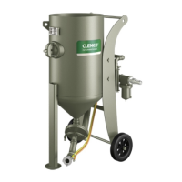
2.3 Connect Conveying Hose
2.3.1 Connect flexible conveying hose between the
collector and exhaust tube, located on the outside rear
wall of the cabinet.
2.4 Ground Cabinet
2.4.1 To prevent static electricity build up, attach an
external grounded wire from an earth ground to the
grounding lug on the left rear of the cabinet.
2.5 Final Assembly
2.5.1 Plug the collector’s power cord into the socket
on the cabinet light switch box. Turning the collector
switch on will enable the light switch to control the
collector motor.
2.5.2 Position the foot pedal on the floor at the front of
the cabinet.
2.5.3 A package of 5 cover lenses is supplied with the
cabinet. To install a cover lens, remove the adhesive
backing and apply the lens to the clean, dry, inner
surface of the view window per Section 5.3. When the
cover lens becomes pitted or frosted, replace it.
2.5.4 Plug the cabinet power cord into a grounded,
120-volt outlet.
3.0 OPERATION
3.1 Media Loading and Unloading
3.1.1 Media Loading: Pour clean dry media directly
through the crate, into the cabinet hopper. Do not load
the hopper over 1/4 full. Use less media if the parts
being blasted cause media to be quickly contaminated.
3.1.2 Media Unloading: Place an empty container
under the metering valve and unscrew the plastic plug
from the metering valve. If media doesn't flow, it has
caked. Open the cabinet door and stir media until it
starts to flow. Replace the plug when the cabinet is
empty.
3.2 Loading and Unloading Parts
WARNING
Use solid fixturing to hold heavy parts in place.
Do not remove lift equipment until the part is
adequately supported to prevent movement.
Moving heavy, unsupported parts may cause
them to shift or topple, and cause severe injury.
3.2.1 Load and unload parts through either door.
3.2.2 Parts must be free of oil, water, grease, or other
contaminants that will cause media to clump, or clog the
filter.
 Loading...