BNP PRESSURE BLAST CONVERSION KIT Page 4
1.8.5 Glass Bead: Most beads are treated to ensure
free-flow operation even under moderately high humidity
conditions. Glass beads subjected to excessive moisture
may be reused after thorough drying and breaking up any
lumps.
1.8.6 Fine-mesh Media: The optional adjustable vortex
cylinder is should be installed when using 200-mesh and
finer media. NOTE: The adjustable vortex cylinder is
standard on pull-through systems . When using very fine
media (200 mesh and finer), the inlet baffle of the
reclaimer may also need to be removed. Consult the
factory before proceeding with this option.
1.8.7 Lightweight Media: The optional adjustable
vortex cylinder should be used when using all plastic
media, and most agricultural media. NOTE: The adjustable
vortex cylinder is standard on pull-through systems.
1.9 Compressed Air Requirements
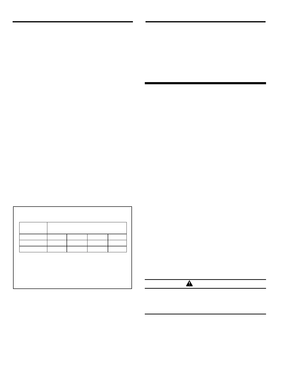
1.9.1 The size of the compressor required to operate
the equipment depends on the size of the nozzle and
blasting pressure. See the table in Figure 3 to determine
the cfm requirements. The table shows air consumption
of nozzles when new. It does not show the
recommended compressor size. As nozzles wear, they
will consume up to 70% to 80% more air. Consult with a
compressor supplier for a suggested compressor size
based on the air consumption.
Compressed Air Consumption *(cfm)
Nozzle Air Pressure (psi)
size 50 60 70 80
1/8" 11 13 15 17
3/16" 26 30 33 38
1/4" 47 54 61 68
* Figures are approximate and for reference only,
and may vary for different working conditions.
Several variables, including media flow and nozzle
wear affect cfm consumption.
Figure 3
1.9.2 The air filter at the blast machine inlet removes
condensed water from the compressed air. Its use is
especially important in areas of high humidity, or when
fine-mesh media are used. Moisture causes media to
clot and inhibits free flow through the metering valve. If
moisture problems persist, an air dryer may be required.
1.10 Electrical Requirements
1.10.1 Electrical requirements depend on the size and
phase of the motor. Standard push thru reclaimers are
supplied as follows:
600 cfm reclaimer: 1 HP, 120/240V, 1-PH, 60 HZ
900 cfm reclaimer: 2 HP, 230/460V, 3-PH, 60 HZ
2.0 INSTALLATION
2.1 General Installation Notes
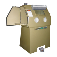
2.1.1 See Figure 1 and 2 for the general arrangement
and Figure 4 for the control line schematic. Select a
location where compressed air and electrical service are
available. The location must comply with OSHA and
local safety codes. Allow for full access to all doors and
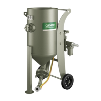
service areas. Ideally, locate the blast machine directly
behind the cabinet with the blast hose connection toward
the cabinet. The reclaimer may be rotated on the blast
machine to enable hose connections with as few bends
as possible. Determine the best location, and position all
units before final assembly.
2.2 Assemble Blast Machine and Reclaimer
2.2.1 Apply adhesive-backed strip gasket to the top of
the flange on the blast machine. Punch out an opening
at each bolt hole.
2.2.2 Place the optional storage segment on the blast
machine. The access door should be on the bottom, and
rotated to allow access. Bolt into place. Apply adhesive
backed gasket to the top flange as described in Section
2.2.1.
2.2.3 Using a lift, raise the reclaimer over the blast
machine assembly, and lower it in place. Attach with
fasteners provided.
Do not work under the reclaimer while it is
hanging from the lifting device. Severe injury or
death could occur if the reclaimer is released
before it is secured to the blast machine.
2.3 Support the Blast Machine
2.3.1 Use ropes or other means to temporarily support
the blast machine and reclaimer during final assembly.
WARNING
 Loading...