BNP PRESSURE BLAST CONVERSION KIT Page 12
8.11.9 Check the 4-way valve per Sections 8.10.4 and
8.10.5.
8.11.10 Inspect the check valve for obstruction or broken
flap.
8.12 Static Shocks
8.12.1 Cabinet and/or operator not grounded. Abrasive
blasting creates static electricity. The cabinet must be
grounded to prevent static build-up. If shocks persist, the
operator may be building up static. Attach a small
ground wire (such as a wrist strap) from the operator to
the cabinet.
9.0 ACCESSORIES AND REPLACEMENT
PARTS
9.1 Optional Accessories
Description Stock No.
Storage segment, 16": Fits between the
reclaimer and blast machine. Provides nearly 2
additional cubic feet of media storage .................... 21128
Vortex cylinder assembly, adjustable
for exhauster mounted reclaimer
600 cfm ......................................................... 19062
900 cfm ......................................................... 23047
Flex hose, heavy lined, for heavy usage with
aluminum oxide. Available in 15 ft. lengths only
5" ID ................................................................. 12465
6" ID ................................................................. 12457
Boron carbide nozzle
CTB-2, 1/8" orifice ............................................. 21090
CTB-3, 3/16" orifice ........................................... 21091
CTB-4, 1/4" orifice ............................................. 21092
Lock pins (pkg of 25) for twist-on hose couplings .. 11203
Safety cable, blast hose ......................................... 15012
Manometer kit ......................................................... 12528
Abrasive trap .......................................................... 02011
Conversion kits, Sentinel metering valve
To convert from fine mesh media to coarse .... 22848
To convert from coarse mesh media to fine .... 22849
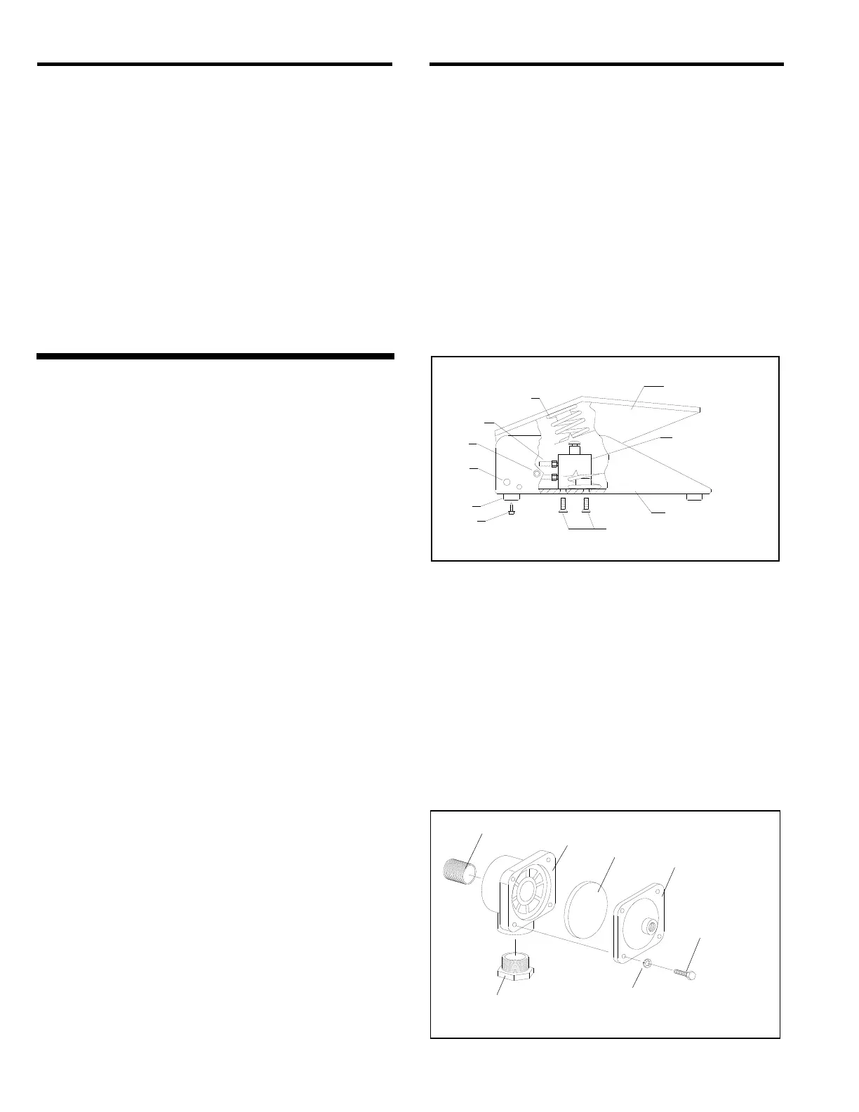
9.2 Foot Pedal Assembly, Figure 5
Item Description Stock No.
(-) Foot pedal assembly, less tubing ................. 20483
1. Top, foot pedal .............................................. 20017
2. Base, foot pedal ............................................ 19991
3. Valve, 3-way n/c ........................................... 20026
4. Drive pin, grooved ........................................ 20109
5. Screw, 1/4 nf x 3/4" soc. hd. ......................... 03086
6. Screw, 10-32 x 1/2" fh .................................. 19571
7. Adaptor, 10-32 thrd. x 1/8" barb ................... 11731
8. Spring, 1-1/4" x 3-1/2" .................................. 20121
9. Screw, 8-32 x 3/8 thread cutting ................. 11389
10. Bumper, rubber (feet) ................................... 21522
Figure 5
9.3 1" Diaphragm Outlet Valve, Figure 6
Item Description Stock No.
(-) 1" Diaphragm outlet valve, complete ............ 03371
1. Nipple, 1" x close .......................................... 01701
2. Diaphragm, outlet valve ................................ 06149
3. Lock washer, 1/4" ......................................... 03117
4. Cap screw, 1/4"x 1" ...................................... 03053
5. Cap, diaphragm outlet .................................. 03393
6. Body, diaphragm outlet ................................. 06135
7. Bushing, 1-1/4" x 1" ...................................... 01804
Figure 6
1
8
3
2
5
4
6
7
9
10
1
2
6
5
3
4
7
 Loading...