7
An after-image is maintained more easily when the
background is alternating light and dark, therefore
t
he automatic flashing unit should be used
immediately after the patient has been subjected
to the above. This is done simply by rotating still
further the selector switch until the stop marked
‘Both eyes’ is reached. If normal retinal
correspondence exists, the patient will now see an
after-image in the form of a cross + but if the
retinal correspondence is abnormal the
after-image may be a variant of one or other of the
following: I- or -l. The result should be given
graphically and the images labelled accordingly to
the eye concerned.
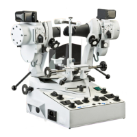
18. The automatic flashing unit
(Models 2001 and 2002 only).
The unit is fitted to Synoptophore Models 2001
and 2002. The same unit is used on both
instruments. From paragraph 14 above, you will
have understood that the flashing unit will only
operate the 6V lamps when the selector switch
(131) is turned to one of the three automatic
flashing positions (red engraving). The three
positions are ‘Both eyes’ ‘Left eye and ‘Right eye’.
If both eyes are to be flashed, for the purpose of
maintaining an after-image, the switch (133) can
be set at Simultaneous or at Alternating. If only
one eye is being flashed, it makes no difference
what position the switch is in. The speed of the
flash, or to put it another way, the length of the
light and the dark phase, is variable. The fastest
flashing (shortest phases) is obtained when switch
(132) is set at ‘Rapid’. In that position the light and
dark periods are of equal length. To make the
flashing slower, switch (137) is moved to the
‘Variable’ position and the two controls (134) are
now in circuit. One of these controls determines
the length of the light phase and the other
determines the length of the dark phase. The
engraved figures surrounding these two controls
do not represent actual lengths of time of the
phase. However, the high figures do indicate long
phases and the low figures short phases. If,
therefore, a slow flash (long phases) is required,
with light and dark of equal length, the controls
would be set at ‘10’. When set at ‘0’, the phases
would be short; when at ’5’, medium, and so on. If
the relationship between light and dark is required
to be unequal, then the two controls would be set
as different figures. A little experimentation will
soon show what a great variety of flashing can be
obtained. Although the figures are empirical, they
are of value in as much as they allow the operator
to preset the device. Moreover, it may be found
that a patient retains an after-image longer with a
certain light/dark relationship. The figures can
thus be recorded for future use.
19. Haidinger’s Brushes
(2001 Model only).
Haidinger’s brushes are phenomena caused by
polarised light falling upon the macula. As the
centre of the brush coincides with the fovea, the
use of the phenomenon is indicated in cases of
e
ccentric fixation and abnormal retinal
correspondence, for the patient, when he has
learned to recognise the brush, can then be made
aware of the spatial projection of the fovea and
use this point for fixation.
The device in Synoptophore Model 2001 consists
of two motorised units (138) which are inserted
into the slots in the optical tubes adjacent to the
slide carriers, when the brushes are required. At
other times the motor units are housed in the
special compartments of the instrument table. In
addition to the removable parts, the
Synoptophore itself has certain other built-in
features which are necessary for Haidinger’s
brush treatment. These are the iris diaphragms
(140), the high intensity light switches (130) and
the slots in the tubes to take additional blue filters
at (139).
Haidinger’s brushes can be presented to the
patient’s left eye, right eye both eyes together.
They can be used with after-image or with
ordinary slides or with both after-images and
slides. Special slides in black and white,
on transparent film are available, and are better
than coloured slides, for this purpose.
The motor unit (138) or units are inserted into the
slots adjacent to the slide carriers (see
illustration). The On/Off switches (135) on the
control unit are turned on and the motors then
commence to rotate the polaroid discs. Each
motor unit has its own speed control (137) and
each has its own reversing switch (136). Some
patients will see the brushes more easily than
others and the speed of rotation may have some
bearing on this. The reversing switches are useful
as a test to ensure that the brush is really being
observed.
The purpose of the iris diaphragms (140) is to
reduce the field of vision and to test whethter a
patient who superimposes the Haidinger’s brush
and the target really fixes centrally or not. If
superimposition remains when the aperture is at
its smallest, the patient must be viewing the target
with the fovea. If a patient who otherwise sees the
brush and target fails to do so at the smallest
aperture setting fixation is not foveal.
If the Haidinger’s brush is presented to one eye
only, it is necessary to place a blue filter into the
slot (139) before the other eye, so that two eyes
are ‘balanced’. If the filter is not inserted, the white
light will dominate the blue.
Synoptophore Instructions
 Loading...