Page 8 of 26
Clenergy SPH Installation and Operation Manual
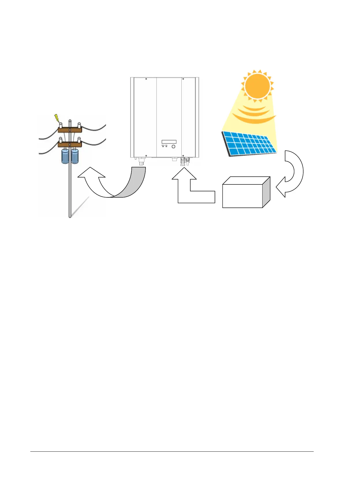
2. PV installation system diagram
PV array: Provides DC power to the SPH inverter. A DC
Disconnect Switch or optional Solar Concentrator is usually
fitted between the PV array and the SPH inverter.
SPH inverter: Converts DC power from the PV array into AC power. The AC
(Alternating Current) power is supplied to the electric grid (AC
utility). The SPH inverter uses Maximum Peak Power Tracking
(MPPT) to optimize the PV array operation and deliver
maximum power to the electric grid.
Connection: The “interface” between the SPH inverter and the
System Grid usually consists of an electrical breaker or fuse and
terminals for connection. It may also contain a disconnect
switch. For proper safety, this part must be designed by a
qualified electrician or electrical installation technician.
Utility: The electricity supply from the main electric grid
system must be single phase 220V to 250V, 50Hz
or 60Hz.
 Loading...